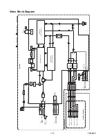

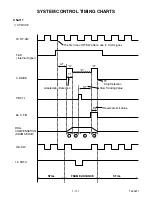
1-7-9
T5553TR1
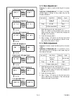
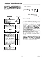
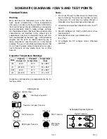
Check Fuse (F601) is blown
out or not.
If fuse is blown out,
do repair method #1
Check whether the primary
rectifying DC of the Switching
power supply has an output.
(Reading should be about 168V.
Voltage of the 105V line
higher than normal?
The transformer of the power
supply makes a higher sound
or the oscillation wave form is
abnormal.
(E.g. intermittent oscillation)
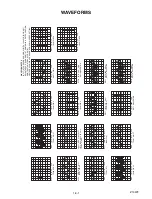
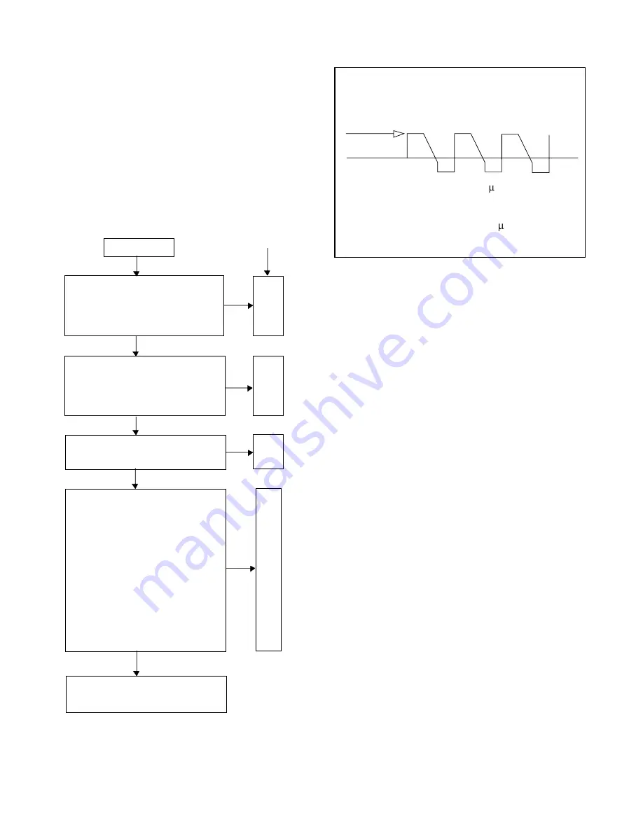
Connect the positive probe of
oscilloscope to the pin 16 of
T601, then connect the negative
probe to the pin 12. Observe the
waveform and check to see if
the waveform is out of limit of
value shown in Fig.1.
There is no problem on the
SW power supply
CHECK
#1
#2
#3
#4
Repair method
NO
NO
NO
YES
YES
YES
YES
NO
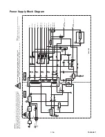
Power Supply Trouble Shooting Guide
It is highly recommended that a variable isolation
transformer which can monitor current be used.
(Alternatively a variable AC source which monitors
current will do). Read directions below before
power is added!
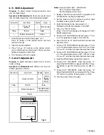
Repair method #1
(Power must be off)
Short circuit in the secondary side. check diode D613,
D614, D616, D617 and D618, switching transistor
(Q601), control transistor (Q602), diode and resistor
replace as necessary.
Disconnect 105V diode (D613), 25V diode (D614), 8V
diode (D616), 12V diode (D617), 12V diode (D618)
and Check the load continuity of 105V line, 25V line,
8V line, 12V line through a tester (resistance range).
If the tester indicates a lower resistance value around
0 ohm, the line is short-circuited.
Before repairing the switching power supply, find out
the short-circuited area of such line and repair it.
If the tester does not indicate any low resistance value
(around 0 ohm), no load is short-circuited and there is
no problem.
Check for any defective parts while the secondary rec-
tifying diodes are disconnected (D613, D614, D616,
D617 and D618) perform a diode check in both for-
ward and reverse directions through a tester.
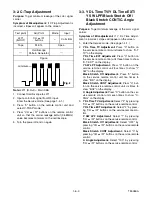
Fig.1
0V
Voltage approx. 5Vp-p
T=Approx. 6 to 14 sec
Oscilloscope setting: 1V/DIV.
2 sec./DIV
Содержание SRC2213W
Страница 17: ...1 5 2 T5505DC S 1 1 REAR CABINET S 1 S 2 Fig 1 Fig 2 1 REAR CABINET S 1 S 2 S 1 S 1 S 1 ...
Страница 18: ...1 5 3 T5505DC Fig 3 2 TRAY CHASSIS 3 DECK UNIT S 3 S 3 S 3 4 MAIN CBA S 6 S 5 S 4 S 6 S 6 S 6 S 7 ...
Страница 19: ...1 5 4 T5505DC Fig 4 S 8 S 8 S 8 S 8 ANODE CAP 5 CRT CRT CBA ...
Страница 22: ...1 5 7 T7505DC ANT 1 REAR CABINET Fig 1 S 1 S 1 S 1 S 2 Fig 2 1 REAR CABINET S 1 S 1 S 2 S 1 S 1 ...
Страница 23: ...1 5 8 T7505DC Fig 3 S 6 S 5 S 4 S 6 S 6 S 6 S 7 S 3 S 3 2 TRAY CHASSIS 3 DECK UNIT 4 MAIN CBA S 3 ...
Страница 24: ...1 5 9 T7505DC Fig 4 S 8 S 8 S 8 S 8 5 CRT CRT CBA ANODE CAP ...
Страница 65: ...1 14 5 T5505PEX Packing SRC2213W X3 X4 X2 TAPE X1 X5 S2 S6 S3 S1 S4 FRONT ...
Страница 66: ...1 14 6 T7505PEX SRC2419 X1 S1 S4 S3 S3 S2 TAPE TAPE X4 X3 X2 S6 S14 FRONT ...
Страница 103: ...SRC2213W SRC2419 T5505UF T7505UF Printed in Japan 2004 03 20 HO ...