
1-5-6
T7505DC
[ SRC2419 ]
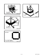
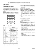
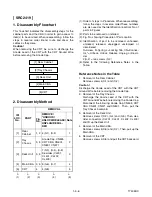
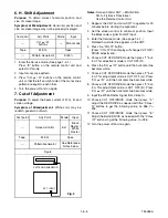
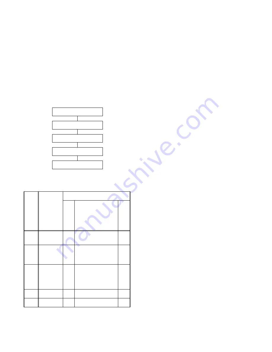
1. Disassembly Flowchart
This flowchart indicates the disassembly steps for the
cabinet parts and the CBA in order to gain access to
item(s) to be serviced. When reassembling, follow the
steps in reverse order. Bend, route and dress the
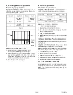
cables as they were.
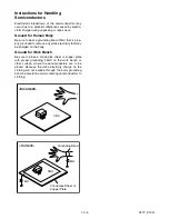
Caution !
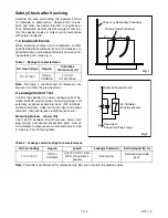
When removing the CRT, be sure to discharge the
Anode Lead of the CRT with the CRT Ground Wire
before removing the Anode Cap.
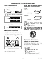
2. Disassembly Method
(1): Order of steps in Procedure. When reassembling,
follow the steps in reverse order.These numbers
are also used as the Identification (location) No. of
parts in Figures.
(2): Parts to be removed or installed.
(3): Fig. No. showing Procedure of Part Location.
(4): Identification of part to be removed, unhooked,
unlocked, released, unplugged, unclamped, or
desoldered.
S=Screw, P=Spring, L=Locking Tab, CN=Connec-
tor, *=Unhook, Unlock, Release, Unplug, or Desol-
der
2(S-2) = two screws (S-2)
(5): Refer to the following Reference Notes in the
Table.
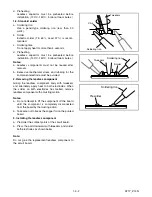
Reference Notes in the Table
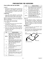
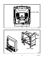
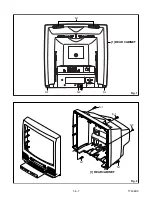
1. Removal of the Rear Cabinet.
Remove screws 4(S-1) and (S-2).
Caution !
Discharge the Anode Lead of the CRT with the CRT
Ground Wire before removing the Anode Cap.
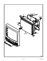
2. Removal of the Tray Chassis.
Discharge the Anode Lead of the CRT with the
CRT Ground Wire before removing the Anode Cap.
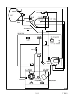
Disconnect the following: Anode Cap, CN505, CRT
CBA, CN601, CN571 and CN801. Then, pull the
Tray Chassis backward.
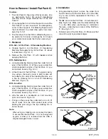
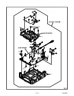
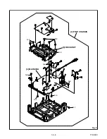
3. Removal of the Deck Unit.
Remove screws 7(S-3), (S-4) and (S-5). Then, des-
older connectors (CL201, CL401, CL402, CL403)
and lift up the Deck Unit.
4. Removal of the Main CBA.
Remove screws 5(S-6) and (S-7). Then, pull up the
Main CBA.
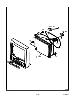
5. Removal of the CRT.
Remove screws 4(S-8) and pull the CRT backward.
ID/
LOC.
No.
PART
REMOVAL
Fig.
No.
REMOVE/
*UNHOOK/
UNLOCK/RELEASE/
UNPLUG/DESOL-
DER
Note
[1]
Rear
Cabinet
1, 2 4(S-1), (S-2)
1
[2]
Tray
Chassis
3, 5
Anode Cap, CN505,
CRT CBA, CN601,
CN801, CN571
2
[3]
Deck Unit
3, 5
7(S-3), (S-4), (S-5)
Desolder (CL201,
CL401, CL402,
CL403)
3
[4]
Main CBA
3, 5 5(S-6), (S-7)
4
[5]
CRT
4
4(S-8)
5
↓
(1)
↓
(2)
↓
(3)
↓
(4)
↓
(5)
[5] CRT
[4] Main CBA
[3] Deck Unit
[2] Tray Chassis
[1] Rear Cabinet
Содержание SRC2213W
Страница 17: ...1 5 2 T5505DC S 1 1 REAR CABINET S 1 S 2 Fig 1 Fig 2 1 REAR CABINET S 1 S 2 S 1 S 1 S 1 ...
Страница 18: ...1 5 3 T5505DC Fig 3 2 TRAY CHASSIS 3 DECK UNIT S 3 S 3 S 3 4 MAIN CBA S 6 S 5 S 4 S 6 S 6 S 6 S 7 ...
Страница 19: ...1 5 4 T5505DC Fig 4 S 8 S 8 S 8 S 8 ANODE CAP 5 CRT CRT CBA ...
Страница 22: ...1 5 7 T7505DC ANT 1 REAR CABINET Fig 1 S 1 S 1 S 1 S 2 Fig 2 1 REAR CABINET S 1 S 1 S 2 S 1 S 1 ...
Страница 23: ...1 5 8 T7505DC Fig 3 S 6 S 5 S 4 S 6 S 6 S 6 S 7 S 3 S 3 2 TRAY CHASSIS 3 DECK UNIT 4 MAIN CBA S 3 ...
Страница 24: ...1 5 9 T7505DC Fig 4 S 8 S 8 S 8 S 8 5 CRT CRT CBA ANODE CAP ...
Страница 65: ...1 14 5 T5505PEX Packing SRC2213W X3 X4 X2 TAPE X1 X5 S2 S6 S3 S1 S4 FRONT ...
Страница 66: ...1 14 6 T7505PEX SRC2419 X1 S1 S4 S3 S3 S2 TAPE TAPE X4 X3 X2 S6 S14 FRONT ...
Страница 103: ...SRC2213W SRC2419 T5505UF T7505UF Printed in Japan 2004 03 20 HO ...