Operating Instructions
22
Connection procedure
Proceed as follows:
1. Unscrew the housing cover
2. Remove any existing display and control module by turning it gently anti-clockwise
3. Undo the union nut on the cable screw connection
4. Strip the connection cable over a length of approx. 10 cm (4 in), strip the core ends over a length of
approx. 1 cm (0.4 in)
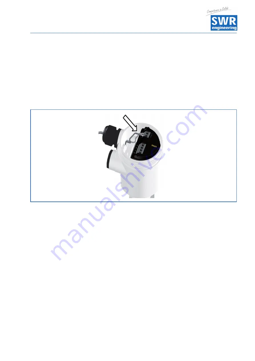
5. Push the cable through the cable screw connection into the sensor
6. Place the core ends into the terminals as shown in the connection diagram
Fig. 30: Connection steps 5 and 6
Information
Solid cores and flexible cores with wire-end ferrules may be inserted straight into the terminal openings.
Flexible cores without end ferrules should be pressed on to the terminal head with a small slotted screwdriver
to release the terminal opening. Removing the slotted screwdriver will close the terminals again.
Further information about the maximum core cross-section is available in the sections entitled
"
Technical data / Electromechanical data
"
7. Check that the cables are correctly positioned in the terminals by pulling them gently.
8. Connect the shield to the internal earth terminal and the external earth terminal to the equipotential
bonding system.
9. Tighten the union nut on the cable screw connection The sealing ring must completely surround the cable.
10. Reinstall any existing display and control module.
11. Screw on the housing cover.
This completes the electrical connection.


