background image


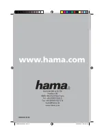
Figure 5.1-14  the Positions of Audio Meter 

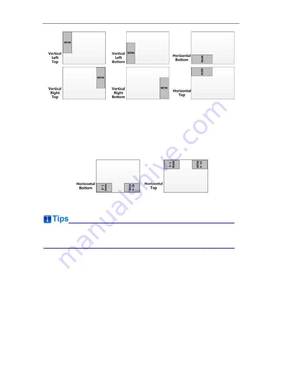
Particularly, if the 

METER SELECT

 item is set as 

G1-4

, there will be 16 channels displayed in 

audio meter, and if the 

METER DIRECTION 

is 

Horizontal

, the audio meter will display two meters 

separately on both sides of the screen. One displays 8 channels (1~8) on the bottom or top left of 

the screen, and the other displays 8 channels (9~10) on the bottom or top right of the screen, the 

bottom or top is decided by 

METER POSITION

, as shown in Figure 5.1-15: 


Figure 5.1-15  the Positions of the 16-channels Meter 


  The prerequisite for the available settings of the display mode and the position of audio meter 

is that the 

AUDIO METER

 is 

ON


DISPLAY Menu 

The DISPLAY menu items are used to set your status information, wave form, vector, line wave, 

AFD and time code preference displayed on the screen, the menu items are as shown in Figure 

5.1-16: 

Содержание FM-24DCI

Страница 1: ...Model FM 24DCI 24 DCI P3 Gamut Post Production Monitor User Manual Ver A SWIT Electronics Co Ltd Please read this User Manual throughout before using...

Страница 2: ...including scratches cracks or other damage to the LCD screen or other externally exposed parts The LCD dot defects are not over three Any damage caused by using third party power adaptors Any damage o...

Страница 3: ...disconnect the power cable under the following situations A If you do not operate this monitor for a period of time B If the power cable or power adaptor is damaged C If the monitor housing is broken...

Страница 4: ...sries 1 Battery plate V mount 2 Desktop Stand Feet 3 Sun hood 4 Protective Glass 5 Power cable 1 Hanger Features 24 inch 1920x1200 10 bit LCD 12 bit process 100 DCI P3 3G HD SD SDI HDMI monitoring Bui...

Страница 5: ...2 Installation Dimension Front Panel Side View Rear Panel Top View...

Страница 6: ...3 Installation instructions of accessories Desktop Stand Feet...

Страница 7: ...Sun hood Protective Glass...

Страница 8: ...Hanger It provides an inch screw thread hanger as an optional accessory The hanger provides two sorts of screw thread 3 8 inch screw thread a total of 4 1 4 inch screw thread a total of 8...

Страница 9: ...LLY Function of Control Buttons INPUT Selection Button Press INPUT button and toggle or use the UP DOWN button to select and display the corresponding signal input to each connector SDI1 monitor the S...

Страница 10: ...lay mode the signal source for the main picture is set by INPUT button while the slave picture s is set through the CONFIG SUB IN SELECT item in main menu refer to 4 1 7 CONFIG Menu for the details Fu...

Страница 11: ...enu Press again to clear the MAIN menu UP Used to navigate on screen menu Toggle this button to select the previous item or increase the item value DOWN Used to navigate on screen menu Toggle this but...

Страница 12: ...dB 16 BRIGHTNESS Adjust the image brightness 0 100 50 CONTRAST Adjust the image contrast 0 100 50 CHROMA Adjust the image monochroma 0 100 50 The Adjust menu will be closed automatically ten seconds a...

Страница 13: ...to this interface to provide power to the device The specification is 100 240V 50 60Hz AC 15 Power Input DC IN 14 5V One DC input interface from battery powered 14 5V DC 16 Power Output DC OUT 12V BA...

Страница 14: ...he DC input DC IN 14 5V as the unit power supply interface 18 SDI1 IN SDI2 IN BNC Two SDI signal input interfaces support multiple format HD 3G SDI inputs 19 SDI1 OUT SDI2 OUT BNC Two SDI signal outpu...

Страница 15: ...in Figure5 1 Figure 5 1 On Screen Menu The features on the screen are as shown in Figure 5 2 SDI1 1080I59 94 1 2 3 4 5 6 7 8 Status Information Audio Meter Center Marker Timecode Safe Marker Area Mar...

Страница 16: ...nd Sub menu list Menu Control You may control these various functions using MENU UP DOWN and ENTER buttons Follow the instructions below Press UP or DOWN to navigate to a menu item then press Enter bu...

Страница 17: ...active item The item displayed in blue can t be accessed currently You can access the item which is displayed in white except the STATUS settings For example choose the INPUT SELECT SDI1 item the con...

Страница 18: ...ems Default Value Domain Range and Description of the sub item is as shown in Table 5 1 1 Table 5 1 1 The Description of STATUS Menu Items Items Default Value Description INPUT SDI1 Show the current I...

Страница 19: ...ue Domain Range Description SDI1 ON ON OFF Enable Disable SDI1 input SDI2 ON ON OFF Enable Disable SDI2 input LINE1 OFF ON OFF Enable Disable LINE1 input LINE2 OFF CVBS LINE2 Y C LINE2 YPBPR OFF Enabl...

Страница 20: ...RED GREEN BLUE Set the color for the detected edge of images ZEBRA OFF ON OFF Enable Disable the zebra function that will compare the signal luminance with the ZEBRA LEVEL and fill the relevant image...

Страница 21: ...ZOOM CHECK Function LINE2 Select input source format for LINE2 among LINE2 CVBS LINE2 Y C and LINE2 YPBPR For LINE2 CVBS interface LINE2 Y C interface and LINE2 YPbPr interface share the same group o...

Страница 22: ...ettings as shown in Figure 5 1 9 Figure 5 1 9 MARKER Menu The relationship of Items Default Value Domain Range and Description of the sub item is as shown in Table 5 1 3 Table 5 1 3 The Description of...

Страница 23: ...et the luminance to display Safety Marker Center Marker Area Marker and Cross Hatch MARKER MAT OFF OFF Normal background use line for area marker edge only HALF 50 Background darkness BLACK all black...

Страница 24: ...ss of the background When Marker Mat is set as BLACK the outside area of marker is totally in black For example set ASPECT as 16 9 AREA MARKER as 4 3 and SAFETY AREA as 95 then the comparison of these...

Страница 25: ...gnal AUDIO1 output an audio signal that comes from the AUDIO IN1 interface AUDIO2 output an audio signal that comes from the AUDIO IN2 interface UNDEF no sound Select an audio format to output from sp...

Страница 26: ...DIRECTION is set as VERTICAL choose one of the followings BOT LEFT bottom left BOT RIGHT bottom right TOP RIGHT top right TOP LEFT top left When METER DIRECTION is set as HORIZONTAL choose one of the...

Страница 27: ...L line and the lower is the REFERENCE LEVEL line If the audio value is higher than the reference level the audio bar over the reference level line will display in yellow and if the audio value is high...

Страница 28: ...and the other displays 8 channels 9 10 on the bottom or top right of the screen the bottom or top is decided by METER POSITION as shown in Figure 5 1 15 Figure 5 1 15 the Positions of the 16 channels...

Страница 29: ...mation ON is an effective value to AFD DISPLAY item only if the value of STATUS DISPLAY is AUTO or ON WFM FORM TYPE OFF MODE1 WAVE FORM VECT75 MODE2 WAVE FORM VECT100 VECT100 VECT75 WAVE FORM OFF Swit...

Страница 30: ...s if an unsupported signal is input NO SIGNAL appears if no signal is detected Normal the signal format is displayed as 1080i59 94 NTSC or 1280X1024 etc when the input is supported by the monitor Part...

Страница 31: ...window will be displayed at the desired position on the image Figure 5 1 18 WAVE FORM TYPE The WFM POSITION item is used to set the position of the wave form vector display and you can select from lef...

Страница 32: ...ay a time code and set a desired format for time code only available for SDI input The time code is displayed at the bottom center of the screen The mode could be D VITC LTC or VITC and the format is...

Страница 33: ...hether to display the closed caption information Only available when the SUB IN TYPE item is set to be OFF SDI CC TYPE AUTO1 AUTO1 set to 608 VBI for SD SDI input and set to 608 708 for HD SDI input A...

Страница 34: ...CC LOGO Set CLOSED CAPTION CLOSED CAPTION to be ON to display the closed caption transmitted in the signal source then select a transmission standard accordant with the signal input among AUTO1 608 VB...

Страница 35: ...ether to detect 24PsF mode SUB IN TYPE OFF PBP PIP OFF Set the display mode of screen picture SUB IN SELECT SDI2 SDI1 SDI2 LINE1 CVBS LINE2 CVBS LINE2 Y C LINE2 YPBPR HDMI Set the signal input for the...

Страница 36: ...terlaced input signal FAST mode is used to reduce the 3D de interlacing processing time delay set CONFIG FAST MODE to be ON to enable the FAST mode The fast mode feature has the appearance progressive...

Страница 37: ...in an inset window called as the slave picture In PIP mode the relevant position relationship of the main picture and the slave picture is set by CONFIG PIP POSITION item as shown in Figure 5 1 25 Fi...

Страница 38: ...hite balance adjustment and determining shooting angles between two cameras etc In PBP mode the size of the main picture is as large as the slave picture s The picture displayed at the left side is ca...

Страница 39: ...e FUNCTION KEY F1 item and set its value as PBP as shown in Figure 5 1 30 then press F1 to switch the display mode F1 PBP PBP F2 OFF NATIVE FUNCTION F3 4 3 ANAMORPHIC F4 OFF FLASE COLOR F5 OFF FREEZE...

Страница 40: ...G SUB IN TYPE item to set the signal source for the slave picture H FLIP MODE The input signal has been inverted horizontally by a mirror type in H FLIP Display mode Select the menu item CONFIG H FLIP...

Страница 41: ...the monitor screen will recover and lit up automatically OFF set AUTO STANDBY as OFF to disable the auto standby mode Press POWER button when the monitor is in operation mode it will power off the mo...

Страница 42: ...Reset the Gain and Offset values to default values for the current profile set by LOOK PROFILE item USER LUT NAME Display the user LUT name in this value area it supports up to 16 characters LOOK PROF...

Страница 43: ...and Offset values to default values for the current profile selected in the LOOK PROFILE item FUNCTION KEY Menu The FUNCTION KEY menu items are used to assign function to the function buttons F1 F5 o...

Страница 44: ...utton on the front panel of the monitor it will display the Function Menu at the left bottom of the screen and F1 line is highlighted press F1 button again to change the value for FALSE COLOR to be ON...

Страница 45: ...X1080P60 59 94 2048X1080 2048X1080 ANAMORPHIC Press the button to activate the anamorphic mode For HD SDI 3G SDI and 2K signals you could set the de squeeze modes to be OFF 16 9 X1 3 X2 X2 MAG For SD...

Страница 46: ...48X1080P30 29 97 2048X1080P48 47 94 2048X1080P50 2048X1080P60 59 94 OFF 2048X1080 1920X1080 X1 3 2048X1080 1920X762 X2 2048X1080 1920X506 X2 MAG 1290X1080 1920X804 BLUE ONLY Press the button to activa...

Страница 47: ...nput signals simultaneously on the monitor s screen You can specify the relative position of the two input pictures and set the source for each picture refer to 4 1 7 CONFIG Menu for details CC Press...

Страница 48: ...d horizontally by a mirror type FALSE COLOR Press the button to activate the FALSE COLOR display of luminance values This function generates an artificial luminance map of the input source that can be...

Страница 49: ...y inhibition thus you can protect your setting values from being modified and only POWER MENU UP DOWN ENTER buttons are available After enabling the key inhibition function you can only see the KEY IN...

Страница 50: ...English or Chinese for displaying the menu The default language for the menu is ENGLISH The following will teach you how to switch to Chinese Operation Select CONFIG menu Press MENU button to display...

Страница 51: ...ure 5 2 2 Switching the Value of LANGUAGE Exit the Main Menu Click MENU button to exit the Main Menu 6 Specification Specification Values Dimension 24 Dimension WxHxDmm 569 9 x380 7x90 5 Pixel Pitch W...

Страница 52: ...5 X1 Signal Formats HD SDI 1080i50 1080i 59 94 1080i 60 720p50 720p 59 94 720p 60 1035i59 94 1035i 60 3G SDI 1080p50 1080p60 3G SDI HD SDI Input Output Signal Type SMPTE 424M SMPTE 292M SMPTE 297M Con...

Страница 53: ...53...

Отзывы: