background image

GB.COOLDXS.INS.100507

20     www.swegon.com

We reserve the right to alter specifi cations.

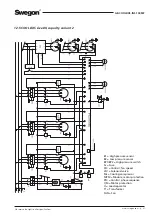
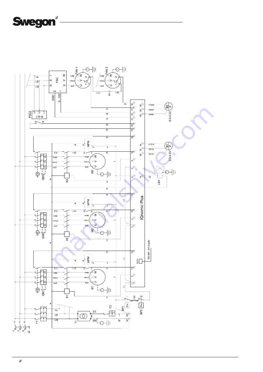
12.4 COOL DXS size 60, capacity variant 2 and size 80, capacity variant 1

B1 = High pressure sensor
B2 = Low pressure sensor
BP1/BP2 = High pressure switch
Fx = Fuse
FSC = Control, fan speed
LSV = Solenoid valve.
Mx = Cooling compressor
MPM = Module, motor protection
PSC = Control, phase sequence
QM = Motor protection
Q = Load separator
T1 = Transformer
FAN = Fan

Содержание COOL DXS

Страница 1: ...GB COOLDXS INS 100507 COOL DXS Cooling Unit Installation and Maintenance Instructions Sizes 12 80 ...

Страница 2: ...art up 12 5 1 2 Starting up 12 5 1 3 Pressure sensor 12 5 1 4 Phase sequence monitor 12 5 1 5 Action if the phase sequence is wrong 12 6 Alarms 12 7 Maintenance 13 7 1 Cleaning 13 7 2 Handling of cooling medium 13 7 3 Periodic inspection 13 7 4 Service 13 8 Troubleshooting and leakage tracing 14 8 1 Troubleshooting Schedule 14 8 2 Leakage Tracing 14 9 Measurement 15 9 1 COOL DXS 12 15 9 2 COOL DXS...

Страница 3: ...nine physical sizes designed for the size 12 80 GOLD air handling units The cooling unit should be placed outside The cooling unit should be connected to the supply air duct behind the GOLD air handling unit Mechanical design All the components conform to refrigeration engineering standards and are pre wired and collected inside a com mon casing The casing is composed of profiled frame members cov...

Страница 4: ...ows from evaporator EVAP further to the suction side by the cooling compressors to once again be compressed Low high pressure sensors B1 B2 measure the pressure of the system in order for the control system to ensure that these are within stipulated limits Solenoid valve LSV ensures that the refrigerant remains in condenser coils when all compressors are idle COND M1 M2 VSL1 EVAP VET1 IPL1 FD1 CON...

Страница 5: ...er it has been operated in Step 3 Size 60 capacity variant 2 to size 80 capacity variant 2 These sizes have three cooling compressors of the same size and are regulated in three steps The cooling capacity is regulated 50 75 100 equivalent airflows tempera tures etc Step 1 Cooling compressor 1 starts if there is a cooling load the cooling compressor with the shortest operating time starts first and...

Страница 6: ...r by the handle and pull the cover carefully outwards N B Have a good grip on the cover so that it will not fall down 2 4 Authorisation Only authorized electricians shall be permitted to install electrical wiring in the cooling unit Servicing inside or reparation of the refrigerant circuit may only be performed by technicians of an accredited cooling firm Other service work in the cooling unit sho...

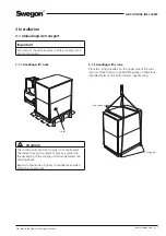
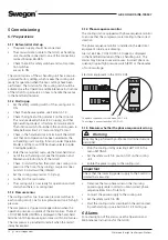
Страница 7: ...e drawing Decal Lifting pipes Sling spreader Important All transport should take place with the cooling unit in horizontal position 3 Installation 3 1 Unloading site transport 3 1 1 Handling with truck Warning The cooling unit s centre of gravity is not centralised The decal showing the centre of gravity is placed on the packaging of the cooling unit when delivered see drawing above Regard to the ...

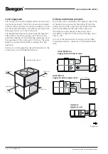
Страница 8: ...ta 3 2 Arrangement The cooling unit should be placed outdoors extra accesso ries are not necessary The GOLD unit can also be placed outdoors with accessories for outdoor installation It is also possible to install the GOLD unit indoors and simply route the supply air duct out to the cooling unit The required free distance for servicing by the inspection side and back side of the cooling unit is 10...

Страница 9: ...ld be insulated according to local regula tions and customary trade standards Sizes 20 80 The size 20 80 Cool DXS cooling unit has rectangular con nection Use slip clamps accessories TBXZ 2 aa 08 slip clamps for jointing to ducts The ducts should be insulated according to local regula tions and customary trade standards 3 3 2 Drainage On the rear of the cooling unit there is a drainage pipe DN25 f...

Страница 10: ...al for incoming earth is situated right next to the safety switch See section 10 Technical data Important Installation must be carried out by a authorised electri cian 4 Electrical connections 4 2 To connect the communication cable Only one communication cable is required for the trans mission of information between the cooling unit and the air handling unit All operation status and other informa ...

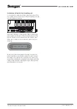
Страница 11: ... the cable to seat properly in the lead through Then refit the lead through to sit correctly Installation of the GOLD air handling unit Communication cable should be connected to any of the bus outlets on the control unit of the air handling unit see encircled area on drawing Use one of the holes in the oblong rubber coated cable gland placed on the rear of the connection hood of the electric cubi...

Страница 12: ...menu The cooling unit is now ready for operation and will start when there is a cooling load 5 1 3 Pressure sensor The cooling unit has two in service pressure switches in each cooling circuit one for low pressure and one for high pressure The compressor is stopped or stepped down when the operation pressure is outside of the limit values The text COOL PRESSURE LIMITING is displayed in the hand he...

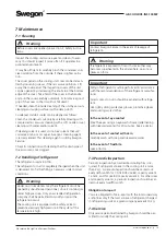
Страница 13: ...Warning Under no circumstances may the refrigerant circuit be opened by unauthorised personnel since it contains gas under high pressure Only an accredited refrigeration company shall be permitted to modify or repair the refrigeration circuit The cooling unit is equipped with a safety valve to prevent excessively high pressure in the system if the temperature is high Important Contact Swegon Servi...

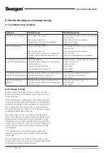
Страница 14: ...e condenser Excessively high ambient air temperature The high pressure switch is defective Check the airflow condenser coil and fan Check the ambient air temperature Check replace Significant freezing on the evaporator The expansion valve is defective or incorrectly set No airflow or too low airflow across the evaporator Defective air cooler Check Replace or adjust setting Check the airflow Check ...

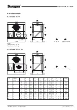
Страница 15: ...3 30 2 2163 2154 1159 1147 1811 201 1200 250 500 50 692 40 1 2413 2404 1159 1147 1999 226 1400 294 600 50 742 40 2 2413 2404 1159 1147 2299 226 1400 294 600 50 910 60 1 2861 2852 1159 1147 2350 350 1600 220 800 50 974 60 2 3308 3298 1159 1147 2350 350 1600 220 800 50 1260 80 1 3756 3747 1159 1147 2599 465 1800 257 1000 70 1364 80 2 3756 3747 1159 1147 2599 465 1800 257 1000 70 1462 E F B1 L1 B2 L2...

Страница 16: ...t Rated cooling power kW Min airflow m3 h m3 s Nominal air flow m3 h m3 s Max airflow m3 h m3 s Power supply Refrigerant charge kg EER energy efficiency ratio 12 1 18 5 2 520 0 7 3 960 1 1 6 840 1 9 3 phase 400V N PE 25A 3 9 2 9 12 2 28 5 2 880 0 8 3 960 1 1 6 840 1 9 3 phase 400V N PE 32A 6 1 3 1 20 1 29 2 880 0 8 6 120 1 7 9 720 2 7 3 phase 400V N PE 32A 6 1 3 2 20 2 43 3 600 1 0 6 120 1 7 9 720...

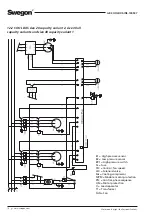
Страница 17: ... DXS size 12 all capacity variants and size 20 capacity variant 1 B1 High pressure switch B2 Low pressure switch BP1 High pressure switch Fx Fuse FSC Control fan speed LSV Solenoid valve Mx Cooling compressor MPM Module motor protection PSC Control phase sequence QM Motor protection Q Load separator T1 Transformer FAN Fan ...

Страница 18: ...nt 2 size 30 all capacity variants and size 40 capacity variant 1 B1 High pressure sensor B2 Low pressure sensor BP1 High pressure switch Fx Fuse FSC Control fan speed LSV Solenoid valve Mx Cooling compressor MPM Module motor protection PSC Control phase sequence QM Motor protection Q Load separator T1 Transformer FAN Fan ...

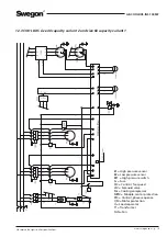
Страница 19: ... capacity variant 2 and size 60 capacity variant 1 B1 High pressure sensor B2 Low pressure sensor BP1 High pressure switch Fx Fuse FSC Control fan speed LSV Solenoid valve Mx Cooling compressor MPM Module motor protection PSC Control phase sequence QM Motor protection Q Load separator T1 Transformer FAN Fan ...

Страница 20: ...apacity variant 2 and size 80 capacity variant 1 B1 High pressure sensor B2 Low pressure sensor BP1 BP2 High pressure switch Fx Fuse FSC Control fan speed LSV Solenoid valve Mx Cooling compressor MPM Module motor protection PSC Control phase sequence QM Motor protection Q Load separator T1 Transformer FAN Fan ...

Страница 21: ...L DXS size 80 capacity variant 2 B1 High pressure sensor B2 Low pressure sensor BP1 BP2 High pressure switch Fx Fuse FSC Control fan speed LSV Solenoid valve Mx Cooling compressor MPM Module motor protection PSC Control phase sequence QM Motor protection Q Load separator T1 Transformer FAN Fan ...

Страница 22: ...nt address Type size Installation connections Inspection measure Approved Done Remarks Installation according to instructions Condensate drainage correctly connected if necessary Electrical connections installed according to instructions Control cable from COOL DXS to GOLD connected according to instructions Rotation direction cooling compressor checked Rotation direction condenser fan checked ...

Страница 23: ...or 1 12 1 13 0 A Prot motor switch Compressor 2 13 0 A 12 2 15 0 A 15 0 A 20 1 15 0 A 15 0 A 20 2 22 0 A 22 0 A 30 1 22 0 A 22 0 A 30 2 22 0 A 35 0 A 40 1 22 0 A 35 0 A 40 2 29 0 A 51 0 A 60 1 29 0 A 51 0 A Prot motor switch Compressor 1 60 2 36 0 A Prot motor switch Compressor 2 36 0 A Prot motor switch Compressor 3 36 0 A 80 1 36 0 A 36 0 A 36 0 A 80 2 51 0 A 51 0 A 51 0 A ...

Страница 24: ...e right to alter specifications Item inspected COOL DXS size Factory preset value Checked value IQnomic function switch 1 12 1 1 IQnomic function switch 2 0 12 2 1 1 20 1 1 3 20 2 1 4 30 1 1 6 30 2 1 7 40 1 1 9 40 2 1 A 60 1 1 C 60 2 1 D 80 1 1 E 80 2 1 F ...

Отзывы: