


GB.COOLDXS.INS.100507
10 www.swegon.com
We reserve the right to alter specifi cations.
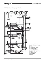
4.1 Power connection
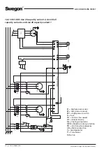
The 400 V incoming power supply to the COOL DXS size
12, capacity variants 1 and 2 and size 20, capacity variant
1 should be a 5-wire system (3 phases, zero and earth).
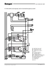
The 400 V incoming power supply to the COOL DXS size
20, capacity variant 2 and up to size 80, capacity variant 2
should be 4-wire system (3 phases and earth).
The cross sectional dimension of the power supply cable
should take into consideration the ambient temperature
and way the cable is run.
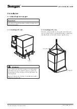
Both inspection covers on the inspection side of the cool-
ing unit can be opened by unscrewing the knobs at the
bottom edge of the covers. Take hold of the cover in the
handle and pull the cover carefully outwards. N.B.! Have a
good grip of the cover so that it will not fall down!
Open the inspection door of the electric cubicle.
Pull the incoming cable for power supply through the
cable gland in the cover panel of the cooling unit, through
the space for compressors and through the cable gland
of the electrical equipment cubicle, see drawing. Locate
the cable in a safe way. Make sure that the cable does not
touch compressors or other components, since surfaces
could be hot or vibrate.
Connect the incoming power supply to the safety switch
block situated in the cubicle, see drawing. The terminal for
incoming earth is situated right next to the safety switch.
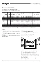
See section 10 Technical data.
Important
Installation must be carried out by a authorised electri-
cian.
4 Electrical connections
4.2 To connect the communication cable
Only one communication cable is required for the trans-
mission of information between the cooling unit and the
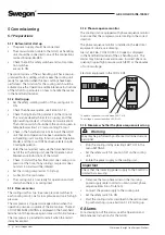
air handling unit. All operation status and other informa-
tion are readily available for viewing in the hand-held
micro terminal of the GOLD air handling unit.
Communication cable is connected in the electrical equip-
ment of the cooling unit and lays coiled behind the in-
spection cover in the space for compressors. Insert the
communication cable and pull it through a predrilled hole
in the cover panel, see drawing. Supplied rubber sleeve is
installed in the predrilled hole. Run the cable in a secure
manner from the cooling unit to the air handling unit. Also
place the cable in a secure manner inside the cooling unit.
Make sure that the cable does not touch compressors or
other components, since surfaces could be hot or vibrate.
N.B.! If the communication cable and the power cable are
run in parallel, they should be at least 100 mm from one
another along the entire stretch.
1
2
34
567
8
9
0
P1
1
2
34
567
8
9
0
P1
1
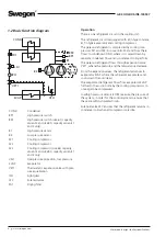
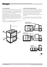
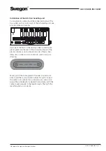
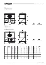
Compressor
The drawing displays COOL DXS from the inspection
side with the inspection covers removed.
Electric cubicle
Cable gland
Cable for
power supply
Communica-
tion cable
Predrilled hole
for communi-
cation cable.
N.b.! Fit the
rubber sleeve
in place
COOL DXS
The block of
the safety
switch