GB.COOLDXS.INS.100507
4 www.swegon.com
We reserve the right to alter specifi cations.
Operation
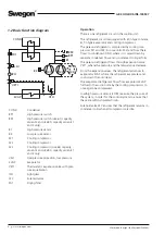
There is one refrigerant circuit in the cooling unit.
The refrigerant circuit is equipped with a fi n type condens-
er, fi n type evaporator and cooling compressor.
The gaseous refrigerant is compressed by cooling com-
pressors M1 and M2 (in some units: M3) and from there
fl ows to condenser COND, where it is cooled down by
separate condenser fl ow and is condensed to liquid form.
The gaseous refrigerant fl ows through expansion valve
VET1, where the pressure and the temperature decrease.
From the expansion valves, the refrigerant advances to
evaporator EVAP, where the refrigerant evaporates and
cools down the outside air.
The evaporated refrigerant fl ows from evaporator EVAP
further to the suction side by the cooling compressors to
once again be compressed.
Low/high pressure sensors B1/B2 measure the pressure of
the system, in order for the control system to ensure that
these are within stipulated limits.
Solenoid valve LSV ensures that the refrigerant remains in
condenser coils when all compressors are idle.
COND
M1
M2
VSL1
EVAP
VET1
IPL1
FD1
COND
Condenser
BP1
High pressure switch
BP2
High pressure switch (size 60, capacity
variant 2 and size 80, capacity variants 1
and 2 only).
B1
High pressure sensor
B2
Low pressure sensor
M1
Cooling compressor
M2
Cooling compressor
M3
Cooling compressor (size 60, capacity
variant 2 and size 80, capacity variants 1
and 2 only)
VSL1
Overpressure protection, low pressure
EVAP
Evaporator
VET1
Thermostatic expansion valve with pres-
sure equalization
IPL1
Sight glass
LSV
Solenoid valve
FD1
Drying fi lter
1.2 Basic function diagram
BP2
M3
B1
B2
BP1
LSV


