9
VAR
Swegon reserves the right to alter specifi cations.
20111011 www.swegon.com
VAR 1
Checking the performance
Start
A 3-minute warm-up period is required when you switch
on the voltage (cold start) before the controller will oper-
ate normally.
Important!
The motor section on the LMV-/NMV D3 MP SWNP has a
release button that in the depressed position enables you
to turn the shaft by hand, but in doing so the controller
loses control over the damper blade position. When you
release the button, the controller automatically synchro-
nises the damper blade position.
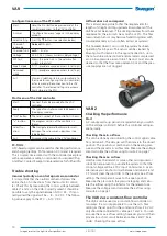
Checking the min. airfl ow
This can be done most simply by disconnecting the white
cable marked 3. The damper will then move to the closed
position. This position is conditional on the bearing pres-
sure and the preset min. airfl ow rate. Measure the voltage
U and calculate the airfl ow using Formula 2 on page 7.
Checking the max. airfl ow
Use the room thermostat or some other control equip-
ment to override the system so that the control voltage
will be a 10 V input on white cable 3. As an alternative
you can short circuit between cables 2 and 3. This will
steer the controller to the preset max. airfl ow setting.
Before short circuiting, you must disconnect the cable
from the room controller. If this is not done, you will
destroy the output on the control equipment. The damper
will move to the open position. Measure the voltage U
and calculate the airfl ow using Formula 2 on page 7.
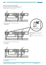
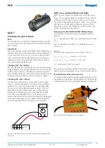
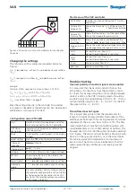
Figure 21. Shows how to connect a voltmeter for checking the
true value.
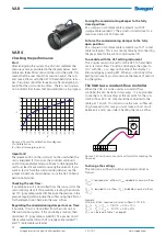
Figur. 22 ZTH-GEN hand-held micro terminal.
VAR 1 as a constant-fl ow controller
VAR 1 can be used as a constant-fl ow controller in two
ways. It is most appropriate to use the min. fl ow setting
as the set point for the constant airfl ow. 24 V AC only
should be connected to cable pair 1 and 2. You can also
use the max. airfl ow setting, however you must then
provide for a short circuit between cables 2 and 3. See
under: Checking the max. airfl ow.
Changing the LMV-/NMV D3 MP SWN settings
The min./max. airfl ow should be calculated and set as
follows:
Q
max
% required max. airfl ow (Q
max
) divided by nominal airfl ow
(Q
nom
).
Qmin % required min. airfl ow (Q
min
) divided by maximum
airfl ow (Q
max
).
Example:
VAR, dim. Ø160, required min./max. airfl ows: 51/119 l/s.
Q
max
% = Q
max
/ Q
nom
=> 119/170 = 0.70 = 70%
Q
min
% = Q
min
/ Q
nom
=> 51/170 = 0.30 = 30%
Q
nom
can be read in Table 1 on page 9
The min./max. settings and the 0-10 or 2-10 signal level
settings can be changed by means of various instruments.
ZTH-GEN hand-held micro terminal
It is simple to check and change the preset airfl ows with the
hand-held micro terminal. The hand-held micro terminal has
a confi guration menu for setting the language and the units.
3,52 V
V DC
U
1
2
3
5
~ w1
NMV-D3MP
SWN


