12
VAR
Swegon reserves the right to alter specifications.
20111011
www.swegon.com
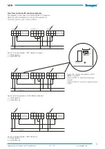
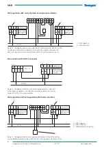
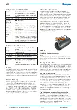
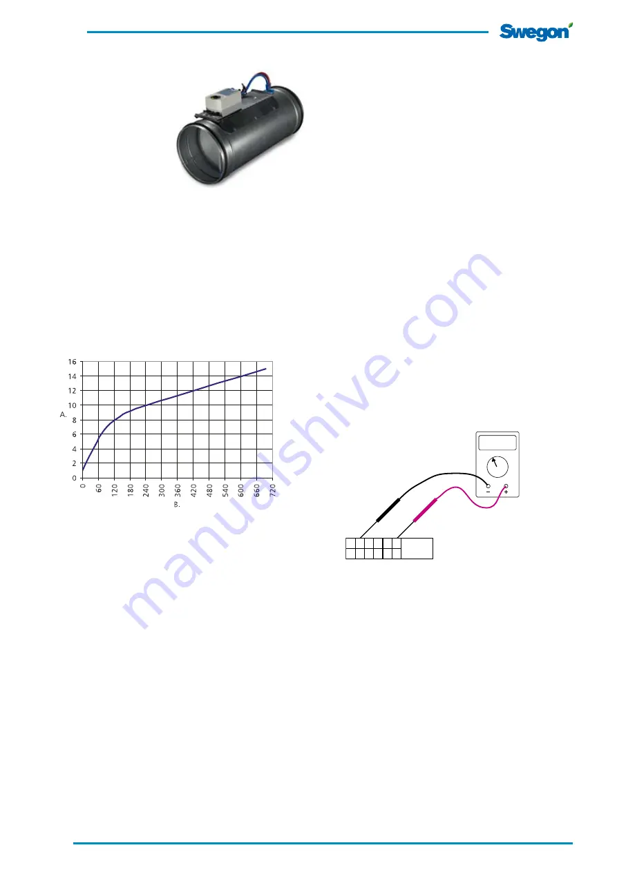
Figure 24. Shows the calibration time diagram.
A = Calibration no.
B = Time after energizing (min).
3,52 V
V DC
1
2
8
9
GLB181.1E/3
G G0
YC UC
6
Y1
7
Y2
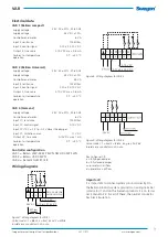
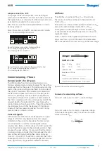
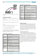
Figure 25. Shows how to connect a voltmeter for checking the
true value.
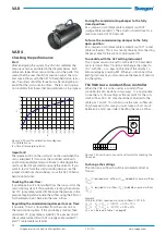
Forcing the commissioning damper to the fully
closed position:
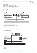
Fit a jumper on G0 (black cable marked 2) with Y2
(orange cable marked 7). The actuator should close for a
maximum period of 150 seconds.
To force the commissioning damper to the fully
open position:
Fit a jumper on G0 (black cable marked 2) with Y1 (violet
cable marked 6). This is most easily done by disconnecting
the grey cable for the control signal marked 9.
To override with the AST setting instrument
The Y signal can also be set from the AST 10 hand-held
micro terminal. Press Y button and change the signal to
10 V with the – or + keys on the side of the display. To
acknowledge by pressing SET. When you disconnect the
Setting instrument, you also remove the means of overrid-
ing the system.
The VAR 4 as a constant-flow controller
When the VAR 4 is to be used as a constant flow
controller,this can be done in two ways . It is appropriate
to use the min. flow setting as the set point for the con-
stant airflow. 24 V AC only should be connected to the
cable pair 1 and 2. You can also use the max. airflow set-
ting, however in this case you must make a short circuit
between 2 and 3, see under Checking the max. airflow.
Important!
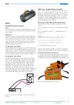
The release button on the unit must not be used when the
unit is energized. If this occurs, the controller will lose its
positioning capability and you will have to de-energize the
unit for at least five seconds to remedy the situation. If you
want to test or force the commissioning damper, use the
jumper connections shown below or use the AST 10 hand-
held micro terminal.
Checking the min. flow:
If possible, zero volt is transmitted from the room unit or the
main control system. If this possibility is lacking, then discon-
nect YC (grey cable, marked 8). Measure the pressure in the
pressure tapping and calculate the airflow using the K-factor
for the relevant size. Check also the max. airflow.
Regulating the commissioning damper to max. flow:
If possible, 10 volt is transmitted from the room unit or
the main control system. If this possibility is lacking, then
disconnect YC (grey cable, marked 8), fit a jumper on G0
(black cable marked 2) with Y2 (orange cable marked 7)
and Y1 (violet cable marked 6).
VAR 4
Checking the performance
Start
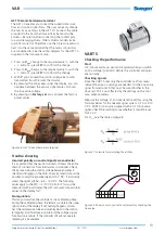
After energizing the system, the VAV unit calibrates the
pressure sensor as illustrated in the diagram below. Each
calibration takes 90 seconds and the unit is then idle. This
means that the user should not precision adjust the min.
and max. airflows with the AST 10 hand-held micro termi-
nal, if required, until after three hours after energizing to
avoid that the unit is idle too often. There is no in-opera-
tion indicator that shows that zero calibration is in progress.
To change the settings
The min./max. airflow should be calculated and set as
follows:
Q
max
% required max. airflow (Q
max
) divided by nominal airflow
(Q
nom
).
Q
min
% required min. airflow (Q
min
) divided by nominal airflow
(Q
nom
).
Example:
VAR, dim. Ø160, required min./max. airflows: 51/119 l/s.
Q
max
% Q
max
/ Q
nom
= 119/170 = 0.70 = 70%
Q
min
% Q
min
/ Q
nom
= 51/170 = 0.30 = 30%
Q
nom
can be read in Table 1 on page 9.


