6
VAR
Swegon reserves the right to alter specifications.
20111011
www.swegon.com
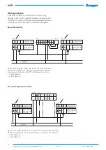
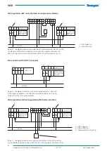
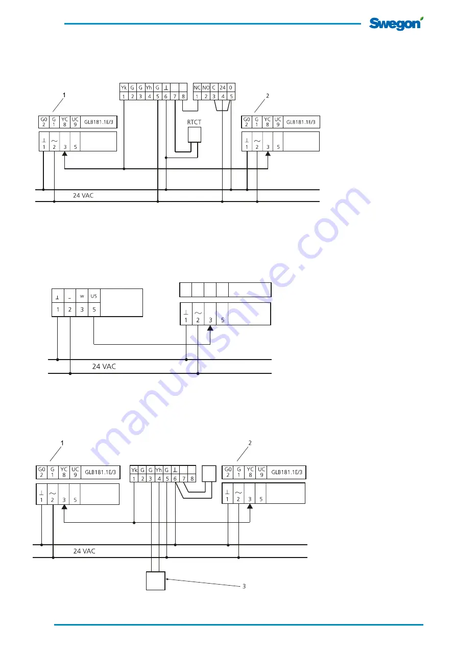
VAV regulation and heat regulation with thermo-actuators
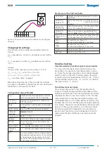
Figure 17. The diagram shows how to wire and refit jumpers of the RTC room ther-
mostat enabling operation of the on/off 24 V VAC thermo-actuator on output YH (4).
LMV-D3-MP SWN
NMV-D3-MP SWN
VRD3 SWN
LMV-D3-MP SWN
NMV-D3-MP SWN
VRD3 SWN
VAR
RTC
VAR
RTCT
-
+
VRD3 SWN
LMV-D3-MP SWN
NMV-D3-MP SWN
VRD3 SWN
VART 5
VAR
G0
2
G
1
YC
8
YC
9
GLB181.1E/3
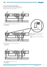
Slave control with VART 5 as master
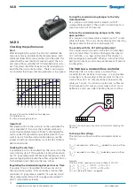
Figure 16. The diagram shows the connections between master – slave unit.
In this wiring configuration, the VAR slave controller should be set to a flow
range of 0-100% of the nominal airflow.
1 = VAR Supply air.
2 = VAR Extract air.
LMV-D3-MP SWN
NMV-D3-MP SWN
VRD3 SWN
LMV-D3-MP SWN
NMV-D3-MP SWN
VRD3 SWN
DETECT O
VAR
VAR
RTC
VAV regulation with room thermostat and presence detector
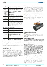
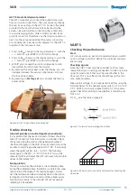
1 = VAR supply air.
2 = VAR Extract air.
3 = Thermo-actuator, heating.
Figure 15. The diagram shows how to wire the RTC room thermostat, DETECT O with
simultaneous control of the extract air. VAV is used for occupancy, otherwise min.
airflow. The figure also shows the alternative with RTCT duct temperature sensor.


