18
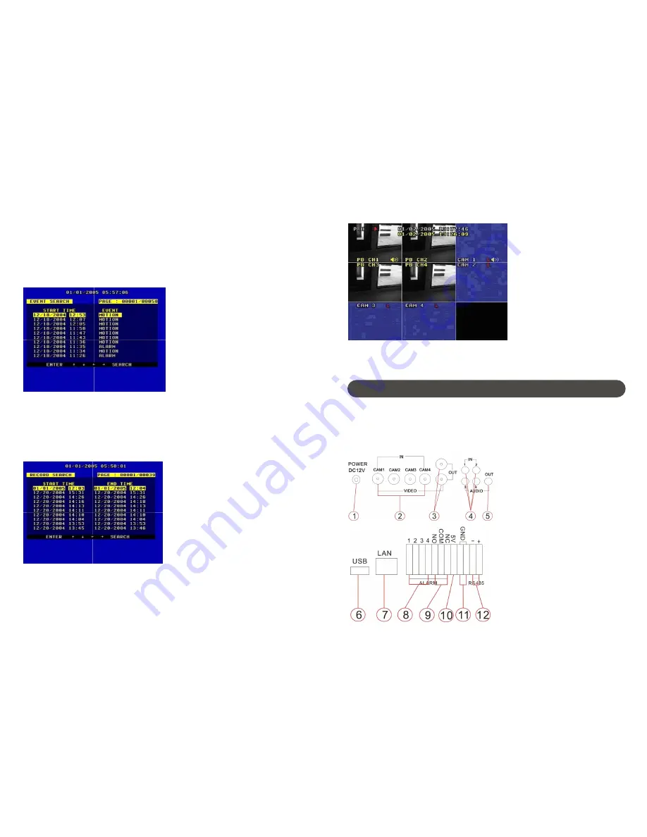
3.TRIP Display
In
Trip Mode
, there will be eight pictures on screen, PB CH1~ PB CH4 are playback
pictures, CAM 1~ CAM4 are live pictures.
Push
TRIP
button or channel buttons to exit
Trip
Mode
.
1.Back Panel and Connection Terminals
The power cord, camera input and video output signal terminals are all at the back of the
DVR4Net. The connections to monitor, camera etc are all handled through the terminals and
sockets on the back panel. The back view of the DVR4Net is illustrated as below.
System Connection
25
Each part of the back panel is illustrated as
below:
1.
DC Power Socket
2.
BNC Video input 1, 2, 3, 4
3.
BNC Video output
4.
Audio input 1, 2, 3, 4
5.
Audio output
6.
USB port
7.
RJ-45 network interface
8.
Alarm input screw terminals
9.
Alarm output screw terminals
10.
+5V screw terminal
11.
GND screw terminal
12.
RS485 screw terminals
9. Event Search
Move the cursor to
Event Search
, then push the
ENTER
button, the event search window
will appear, which is illustrated below.
There are four types of event list:
MOTION
,
ALARM
,
SCH
and
NETWORK
.
MOTION
means motion triggered alarm recording.
ALARM
means
external sensor triggered alarm recording.
SCH
means scheduled time recording.
NETWORK
means network activated recording.
Push the
UP
and
DOWN
button to move the cursor among the event list, push the
LEFT
or
RIGHT
button to see
the
Previous
or
Next
page, and
push the
ENTER
button to play the
segment you have
selected. Push the
SEARCH
button to return to the
Search Play
menu.
10. Start Stop Search
Move the cursor to Start Stop Search, push the
ENTER
button
and the
Start Stop Search
window will appear, which is illustrated below.
All recorded segments are displayed here, push
the
UP
or
DOWN
button to move the
cursor among the segment list then push the
LEFT
or
RIGHT
button to see
Previous
or
Next
page, push
ENTER
button to play the segment you select. Push the
SEARCH
button
again to
return to the
Search Play
menu.


