139
SV 200A User Manual
<result1> -
PEAK
result, depending on the value of BufferP[2] (cf. Table B.1.11)
<result2> -
MAX
result, depending on the value of BufferP[2] (cf. Table B.1.11)
<result3> -
MIN
result, depending on the value of BufferP[2] (cf. Table B.1.11)
<result4> -
RMS
result, depending on the value of BufferP[2] (cf. Table B.1.11)
(3) results of the measurement from the third profile if the corresponding
LOGGER
position was
active (BufferP [3] in Table B.1.11); up to four words are written:
<result1> -
PEAK
result, depending on the value of BufferP[3] (cf. Table B.1.11)
<result2> -
MAX
result, depending on the value of BufferP[3] (cf. Table B.1.11)
<result3> -
MIN
result, depending on the value of BufferP[3] (cf. Table B.1.11)
<result4> -
RMS
result, depending on the value of BufferP[3] (cf. Table B.1.11)
(4) results of
1/1 OCTAVE
analysis if
1/1 OCTAVE
analysis was selected as the measurement
function and the
LOGGER
was active (SpectrumBuff in Table B.1.5); the sequence of words is
written:
<flags> <Octave[1]> <Octave[2]> ÷. <Octave[NOct+NOctTot]>
where:
flags = 1- overload detected, 0 - the overload not detected
Octave[i] - result of
1/1 OCTAVE
analysis (*10 dB); i = 1÷NOct+NOctTot (1÷13)
(5) results of
1/3 OCTAVE
analysis if
1/3 OCTAVE
analysis was selected as the measurement
function and
LOGGER
was active (SpectrumBuff in Table B.1.5); the sequence of words is
written:
<flags> <Terave[1]> <Terave [2]> ÷. <Terave[NT]>
where:
flags = 1- overload detected, 0 - the overload not detected
Terave[i] - result of
1/3 OCTAVE
analysis (*10
dB); i = 1÷NT (1÷34)
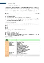
B.2.2 Record with the state of the markers
The record with the state of the markers consists of one word:
<0x8nnn>
in which 12 bits nnn denote the state of the markers:
b11 = state of #12 marker
b10 = state of #11 marker
...
b1 = state of #2 marker
b0 = state of #1 marker
B.2.3 Record with the breaks in the results registration
The record with the breaks in the results registration consists of four words:
<0xB0ii> <0xB1jj> <0xB2kk> <0xB3nn>
in which ii, jj, kk, nn bytes denote 4-bytes counter of left or skipped records: nnkkjjii (ii is the least
significant byte, nn
– the most significant byte).
Содержание SV 200A
Страница 123: ...123 SV 200A User Manual Appendix A REMOTE CONTROL firmware revision 1 x x Under development ...
Страница 153: ...153 SV 200A User Manual Free Field Frequency response of SV 200A ...
Страница 164: ...164 SV 200A User Manual 250 Hz 315 Hz 90 deg 0 deg 90 deg 0 deg 400 Hz 500 Hz 90 deg 0 deg 90 deg 0 deg ...
Страница 165: ...165 SV 200A User Manual 630 Hz 800 Hz 90 deg 0 deg 90 deg 0 deg 1000 Hz 1250 Hz 90 deg 0 deg 90 deg 0 deg ...
Страница 166: ...166 SV 200A User Manual 1600 Hz 2000 Hz 90 deg 0 deg 90 deg 0 deg 2240 Hz 2500 Hz 90 deg 0 deg 90 deg 0 deg ...
Страница 167: ...167 SV 200A User Manual 2800 Hz 3150 Hz 90 deg 0 deg 90 deg 0 deg 3550 Hz 4000 Hz 90 deg 0 deg 90 deg 0 deg ...
Страница 168: ...168 SV 200A User Manual 4500 Hz 5000 Hz 90 deg 0 deg 90 deg 0 deg 5600 Hz 6300 Hz 90 deg 0 deg 90 deg 0 deg ...
Страница 169: ...169 SV 200A User Manual 7100 Hz 8000 Hz 90 deg 0 deg 90 deg 0 deg 8500 Hz 9000 Hz 90 deg 0 deg 90 deg 0 deg ...
Страница 170: ...170 SV 200A User Manual 9500 Hz 10000 Hz 90 deg 0 deg 90 deg 0 deg 10600 Hz 11200 Hz 90 deg 0 deg 90 deg 0 deg ...
Страница 177: ...177 SV 200A User Manual 8 0 kHz 1 1 octave filter 4 0 kHz 1 1 octave filter 2 0 kHz 1 1 octave filter ...
Страница 178: ...178 SV 200A User Manual 1 0 kHz 1 1 octave filter 500 Hz 1 1 octave filter 250 Hz 1 1 octave filter ...
Страница 179: ...179 SV 200A User Manual 125 Hz 1 1 octave filter 63 0 Hz 1 1 octave filter 31 5 Hz 1 1 octave filter ...


