


6-24 ELECTRICAL SYSTEM
IGNITION COIL RESISTANCE
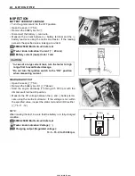
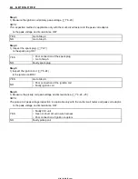
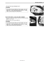
• Remove the leg rear shield. (
!
5-8)
• Disconnect the ignition coil lead wires and spark plug cap.
• Remove the ignition coil.
Measure the ignition coil resistance in both the primary and sec-
ondary windings using the multi-circuit tester. If the resistance in
both the primary and secondary windings is close to the speci-
fied values, the windings are in sound condition.
"
09900-25008: Multi-circuit tester set
(
Tester knob indication: Resistance (
Ω
)
&
Ignition coil resistance
Primary: 0.2 – 0.9
Ω
(
+
Tap –
-
Tap)
Secondary: 11 – 20 k
Ω
(Spark plug cap –
-
Tap)
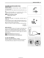
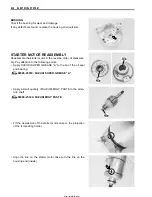
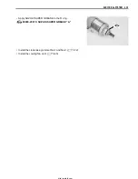
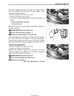
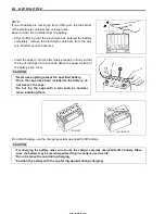
PICKUP COIL PEAK VOLTAGE
• Remove the luggage box. (
!
5-9)
NOTE:
Make sure that all of the couplers are connected properly and
the battery is fully charged.
• Disconnect the CDI unit coil coupler.
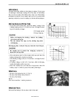
Measure the pickup coil peak voltage in the following procedure.
• Connect the multi-circuit tester with the peak volt adaptor as
follows.
+
Probe: Blue/Yellow lead wire
-
Probe: Ground
"
09900-25008: Multi-circuit tester set
#
• Turn the ignition switch to the “ON” position.
Measure the pickup coil peak voltage while squeezing the front
or rear brake lever and pressing the starter button to turn the
engine for a few seconds.
• Repeat the above procedure a few times and measure the
highest pickup coil peak voltage.
'
Tester knob indication: Voltage (
%
)
&
Pickup coil peak voltage: 2.0 V and more
Before using the multi-circuit tester and peak volt
adaptor, be sure to refer to the appropriate instruction
manual.
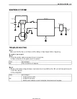
Magneto
Peak volt
adaptor
Bl/Y
Bl/Y
http://mototh.com
Содержание UY125
Страница 4: ...White Page http mototh com ...
Страница 12: ...White Page http mototh com ...
Страница 31: ...PERIODIC MAINTENANCE 2 19 http mototh com ...
Страница 108: ...White Page http mototh com ...
Страница 183: ...ELECTRICAL SYSTEM 6 7 8 Ignition coil 9 Starter relay 0 Starter motor http mototh com ...
Страница 214: ...White Page http mototh com ...
Страница 234: ...7 20 SERVICING INFORMATION CLUTCH TRANSMISSION DRIVE BELT INSTALLATION 1 1 1 1 1 Remove excess grease http mototh com ...
Страница 235: ...SERVICING INFORMATION 7 21 COOLING FAN INSTALLATION 33 N m 3 3 kgf m 10 N m 1 0 kgf m http mototh com ...
Страница 236: ...7 22 SERVICING INFORMATION FUEL TANK INSTALLATION Fuel tap Vacuum hose Fuel hose Clip http mototh com ...
Страница 241: ...SERVICING INFORMATION 7 27 REAR BRAKE CAM LEVER INSTALLATION 33 40 35 Match Match Match Set position http mototh com ...
Страница 243: ...SERVICING INFORMATION 7 29 SEAT HINGE INSTALLATION 96 Seat Assy E ring RH LH FWD http mototh com ...
Страница 244: ...7 30 SERVICING INFORMATION FRONT WHEEL UY125 5 J _ http mototh com ...
Страница 245: ...SERVICING INFORMATION 7 31 FRONT WHEEL UY125S Clearance 1 mm http mototh com ...
Страница 246: ...7 32 SERVICING INFORMATION REAR WHEEL http mototh com ...
Страница 258: ...Prepared by August 2005 Part No 99500 31310 01E Printed in Thailand 260 THAI SUZUKI MOTOR CO LTD http mototh com ...