4-10 FUEL AND LUBRICATION SYSTEM
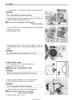
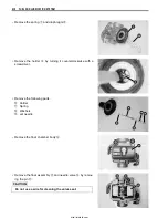
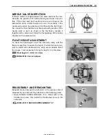
• Remove the spring
7
and diaphragm
8
.
• Remove the holder
9
by turning it counterclockwise with a
screwdriver.
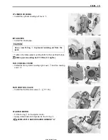
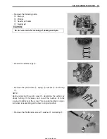
• Remove the following parts.
0
Holder
A
Spring
B
Washers
C
Jet needle
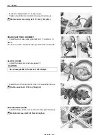
• Remove the float chamber body
D
.
• Remove the float assembly
E
and needle valve
F
by remov-
ing the pin
G
.
%
Do not use a wire for cleaning the valve seat.
http://mototh.com
Содержание UY125
Страница 4: ...White Page http mototh com ...
Страница 12: ...White Page http mototh com ...
Страница 31: ...PERIODIC MAINTENANCE 2 19 http mototh com ...
Страница 108: ...White Page http mototh com ...
Страница 183: ...ELECTRICAL SYSTEM 6 7 8 Ignition coil 9 Starter relay 0 Starter motor http mototh com ...
Страница 214: ...White Page http mototh com ...
Страница 234: ...7 20 SERVICING INFORMATION CLUTCH TRANSMISSION DRIVE BELT INSTALLATION 1 1 1 1 1 Remove excess grease http mototh com ...
Страница 235: ...SERVICING INFORMATION 7 21 COOLING FAN INSTALLATION 33 N m 3 3 kgf m 10 N m 1 0 kgf m http mototh com ...
Страница 236: ...7 22 SERVICING INFORMATION FUEL TANK INSTALLATION Fuel tap Vacuum hose Fuel hose Clip http mototh com ...
Страница 241: ...SERVICING INFORMATION 7 27 REAR BRAKE CAM LEVER INSTALLATION 33 40 35 Match Match Match Set position http mototh com ...
Страница 243: ...SERVICING INFORMATION 7 29 SEAT HINGE INSTALLATION 96 Seat Assy E ring RH LH FWD http mototh com ...
Страница 244: ...7 30 SERVICING INFORMATION FRONT WHEEL UY125 5 J _ http mototh com ...
Страница 245: ...SERVICING INFORMATION 7 31 FRONT WHEEL UY125S Clearance 1 mm http mototh com ...
Страница 246: ...7 32 SERVICING INFORMATION REAR WHEEL http mototh com ...
Страница 258: ...Prepared by August 2005 Part No 99500 31310 01E Printed in Thailand 260 THAI SUZUKI MOTOR CO LTD http mototh com ...

