ENGINE 3-52
ENGINE REASSEMBLY
Reassemble the engine in the reverse order of disassembly.
The following steps require special attention or precautionary
measures should be taken.
NOTE:
Apply engine oil to each running and sliding part before reas-
sembling.
CRANKSHAFT
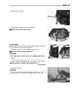
• When installing the crankshaft into the left crankcase, it is
necessary to pull its left end into the left crankcase with the
special tools.
\
09910-32812: Crankshaft installer
09910-32860: Crankshaft installer spacer
09911-11310: Attachment
CRANKSHAFT SHIM SELECTION
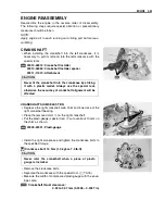
• Degrease the right crankshaft web, shim and inner race of the
right crankshaft bearing.
• Place the removed shim
1
on the right crankshaft.
• Put the plasti-gauge (special tool)
2
cut out about 10 mm on
the shim as shown.
\
09900-22301: Plasti-gauge
• Install the right crankcase and tighten the crankcase bolts to
the specified torque.
"
Crankcase bolt: 10 N·m (1.0 kgf-m, 7.0 lb-ft)
• Remove the crankcase bolts.
• Separate the crankcase with the special tool. (
3-18)
• Measure the width of compressed plasti-gauge with the enve-
lope scale.
Crankshaft thrust clearance:
0.02 to 0.07 mm (0.0008 – 0.0027 in)
Never fit the crankshaft into the crankcase by striking
it with a plastic mallet. Always use the special tool,
otherwise the accuracy of crankshaft alignment will be
affected.
Never rotor the crankshaft when a piece of plasti-
gauge is installed.


