Surtek CE712 Скачать руководство пользователя страница 13

13

E N G L I S H •

User's manual

REMOVING THE PLANER BLADES

To remove the planer blades, follow the steps 
outlined below:

        WARNING: 

Unplug your planer from the 

power source before removing the planer 
blades.

• Remove the chip guard by removing the wing 

nut on each side.
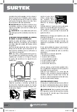
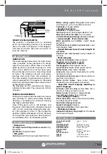
1. Loosen the lock bar 
(Fig.1-B) and blade 
by turning the lock 
screws (A) clockwise. 
The blades are spring 
loaded, and will push 
out when the assem-
bly is loosened. 
2. Take out the blade 
(C), and then the 
blade lock bar (B).

INSTALLING THE PLANER BLADES

        WARNING: 

Unplug your planer from the 

power source before removing the planer 
blades. To install the planer blades, follow the 
steps outlined below:

• Remove the blades according to the instruc

-

tions for  REMOVING THE PLANER BLADES
• Fit the blade lock bar (B) into the slot on the 

cutterhead.

• Fit the blade into the slot on the cutterhead, 

and tighten the lockbar blade assembly by 
turning the screws counter clockwise. Make 
sure the blade is facing the correct direction.

•  Set  the  blade  heights  according  to  the  in

-

structions as shown below. The blade height 
must be reset every time the blades are taken 
out for any reason.
NOTE: Be sure to replace the chip guard after 
blades are installed.

SETTING THE BLADE HEIGHT

To obtain a blade projection of 1.5mm, place 
the blade setting gauge (Fig.1-E) on the cut-
terhead with both guides resting firmly against 
the blade. Loosen the assembly by turning 
the 7 screws (A) clockwise with an open end 
wrench.
When the blade is pressed to the required 
height by guides on the gauge, retighten the 
assembly by turning the screws counter clock-
wise. Make sure all seven lock screws are tight-
ened securely.

        WARNING: 

The blade edge is very suscep-

tible to chipping. Use caution when handling 
the gauge near the blades to avoid damaging 
them.

      WARNING: 

The assembly must be tightened 

securely to prevent accidents during planing.

MAKING THE CUTTERHEAD AND WORKTA-
BLE PARALLEL

Plane a workpiece and measure thickness after 
the cut. If the thickness is not the same on both 
sides of the workpiece, perform the following 
action. Adjust the cutter shaft and the work-
table so they are parallel. The tools used for 
checking are shown below;

NOTE:

 Please use hardwood to make a tool 

guage block according to the size shown in the 
figure 2. Make the adjustments as per the fol-
lowing procedures.

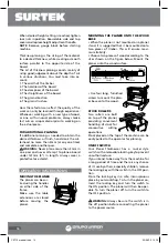
Remove height adjustment handle and both 
top and side covers by removing allen screws 
(Fig.3) to expose height adjustment lock nuts. 
(Fig.4) Loosen adjustment lock nut. 

Adjust height nut up 
or down as required 
to suit guage block. 
(Fig.5)

Fig.5

Fig.2

Fig.4

Fig.3

Screws

Hand Cranck

Fig.1

Nut of height 

adjust

CE712 manual.indd   13

23/06/15   15:10

Содержание CE712

Страница 1: ...en este manual antes de operar esta herramienta WARNING Read understand and follow the safety rules in this manual before operating this tool CE712 Cepillo de Banco Bench Planer Manual de Usuario y G...

Страница 2: ...ata Troubleshooting Warranty policy Introducci n Normas generales de seguridad rea de trabajo Seguridad el ctrica Extensiones de cable Seguridad personal Uso y cuidado de la m quina Reparaci n Normas...

Страница 3: ...istema de provisi n de potencia con descarga a tierra Evite el contacto del cuerpo con las superficies descargadas a tierra tales como tubos radia dores rangos y refrigeradores Existe un mayor riesgo...

Страница 4: ...n ajuste cambiar acce sorios o guardar la m quina Estas medidas preventivas reducen el riesgo de que la m quina se encienda accidentalmente Cuando la herramienta no est en uso guar delo fuera del alca...

Страница 5: ...CEPILLO Antes de utilizar este trompo familiar cese con todas las caracter sticas de operaci n y seguri dad requeridas PRECAUCI N No permita que la familiari dad con el producto pueda provocar una po...

Страница 6: ...es reajuste el medidor en caso que sea necesario QUITANDO LAS CUCHILLAS DEL CEPILLO Para quitar las cuchillas del cepillo siga los si guientes pasos ADVERTENCIA Desconecte el cepillo de la fuente de p...

Страница 7: ...a las me didas de los bloques Fig 5 Cuando alcance el ajuste de altura adecuado apriete las tuercas de fijaci n en posici n Vuelva colocar las cubiertas de la parte supe rior y lateral y vuelva a colo...

Страница 8: ...interruptor en la posici n OFF apa gado Guarde la llave en un lugar seguro Para en cender el cepillo inserte la llave y accione el interruptor a la posici n ON encendido Podr entonces utilizar el cepi...

Страница 9: ...de las cuchillas no es uniforme Ajuste la proyecci n de las cuchillas El cabezal de corte no est nivelado a la mesa del cepillo Nivele el cabezal de corte con la mesa El espesor de la tabla no es el...

Страница 10: ...risk of electric shock When operating a power tool outside use an outdoor extension cord marked W A or W These cords are rated for outdoor use and reduce the risk of electric shock Replace damaged co...

Страница 11: ...een built by precision Any alteration or modification not specified is misuse and may result in a dangerous condition Is recommendable to use a safety device suit able such a thermal and diferential s...

Страница 12: ...in length Always wear a protec tive face shield To adjust the depth of cut turn the cut terhead raising hand crank in the direction marked on top of the planer The depth of cut adjustment can be read...

Страница 13: ...a blade projection of 1 5mm place the blade setting gauge Fig 1 E on the cut terhead with both guides resting firmly against the blade Loosen the assembly by turning the 7 screws A clockwise with an o...

Страница 14: ...ried using the handles on either side of the frame Make sure the table extensions are closed before moving the planer MOUNTING THE PLANER ONTO THE WOOD BASE When the planer is not mounted on a planer...

Страница 15: ...turn workpiece around Dull blades Sharpen blades Rough raised grain Dull blades Sharpen blades Tool heavy a cut Check proper depth of cut Moisture content too high Dry the wood Cutterhead bearings da...

Страница 16: ...odified by unauthorized or unqualified person Urrea Herramientas Profesionales S A de C V garantiza este producto por el termino de 1 a o en sus piezas componentes y mano de obra con tra cualquier def...

Отзывы: