


5-2
S
uper
W
orkstation 7046A-HR+/7046A-HR+F User's Manual
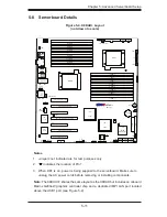
5-2 Serverboard
Installation
This section explains the
fi
rst step of physically mounting the X8DAH+/X8DAH+F
into the SC745TQ-R1400B-SQ chassis. Following the steps in the order given will
eliminate the most common problems encountered in such an installation. To remove
the serverboard, follow the procedure in reverse order.
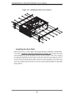
Installing to the Chassis
1. Access the inside of the system by removing the screws from the back lip of
the top cover of the chassis, then pull the cover off.
2. Make sure that the I/O ports on the serverboard align properly with their
respective holes in the I/O shield at the back of the chassis.
3. Carefully mount the serverboard to the serverboard tray by aligning the board
holes with the raised metal standoffs that are visible in the chassis.
4. Insert screws into all the mounting holes on your serverboard that line up
with the standoffs and tighten until snug (if you screw them in too tight, you
might strip the threads). Metal screws provide an electrical contact to the
serverboard ground to provide a continuous ground for the system.
5. Finish by replacing the top cover of the chassis.
Warning:
To avoid damaging the serverboard and its components, do not apply
any force greater than 8 lbs. per square inch when installing a screw into a mount-
ing hole.
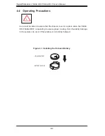
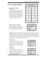
5-3 Connecting
Cables
Now that the serverboard is installed, the next step is to connect the cables to the
board. These include the data cables for the peripherals and control panel and the
power cables.
Connecting Data Cables
The cables used to transfer data from the peripheral devices have been carefully
routed to prevent them from blocking the
fl
ow of cooling air that moves through
the system from front to back. If you need to disconnect any of these cables, you
should take care to keep them routed as they were originally after reconnecting
them (make sure the red wires connect to the pin 1 locations). The following data
cables (with their locations noted) should be connected. (See the layout on page
5-11 for connector locations.)
Содержание SuperWorkstation 7046A-HR+
Страница 1: ...SuperWorkstation 7046A HR 7046A HR F SUPER USER S MANUAL 1 0a...
Страница 5: ...Notes Preface v...
Страница 10: ...Notes SuperWorkstation 7046A HR 7046A HR F User s Manual...
Страница 16: ...1 6 SuperWorkstation 7046A HR 7046A HR F User s Manual Notes...
Страница 30: ...3 4 SuperWorkstation 7046A HR 7046A HR F User s Manual Notes...
Страница 72: ...6 12 SuperWorkstation 7046A HR 7046A HR F User s Manual Notes...
Страница 104: ...7 32 SuperWorkstation 7046A HR 7046A HR F User s Manual Notes...
Страница 106: ...A 2 SuperWorkstation 7046A HR 7046A HR F User s Manual Notes...
Страница 111: ...C 3 Appendix C System Specifications Notes...


