


Chapter 5: Advanced Serverboard Setup
5-21
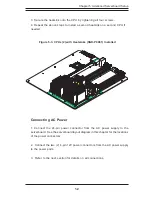
Power Fault
Connect a cable from your power
supply to the U62 header to provide
warning of power supply failure. This
warning signal is passed through the
PWR_LED pin on U66 to indicate a
power failure on the chassis. See
the table on the right for pin defini-
tions.
Note: This feature is only available when
using redundant Supermicro power sup-
plies.
Power Fault Pin Definitions
(U62)
Pin
Number
1
2
3
4
Definition
P/S 1 Fail Signal
P/S 2 Fail Signal
P/S 3 Fail Signal
Reset (from MB)
Wake-On-Ring
The Wake-On-Ring header is desig-
nated J6. This function allows your
computer to receive and "wake-up"
from an incoming call to the modem
when in suspend state. See the
table on the right for pin definitions.
You must have a Wake-On-Ring card
and cable to use this feature.
Wake-on-Ring
Pin Definitions
(J6)
Pin
Number
1
2
Definition
Ground
Wake-up
Fan Header Pin Definitions
(Fan1-Fan8)
Pin
Number
1
2
3
Definition
Ground (black)
+12V (red)
Tachometer
Fan Headers
The i2DML-8G2/i2DML-iG2 has eight
f a n h e a d e r s , d e s i g n a t e d F a n 1
through Fan8. See the table on the
right for pin definitions.
Caution: Fan headers are DC power.
Содержание SuperServer 6123L-8R
Страница 1: ... SUPERSERVER 6123L 8R SUPERSERVER 6123L iR USER SMANUAL 1 0 SUPER RESET NIC 1 NIC 2 RESET NIC 1 NIC 2 ...
Страница 5: ...v Preface Notes ...
Страница 10: ...SUPERSERVER 6123L 8R 6123L iR User s Manual x Notes ...
Страница 18: ...SUPERSERVER 6123L 8R 6123L iR User s Manual 1 8 Notes ...
Страница 23: ...2 5 Chapter 2 Server Installation Figure 2 3 Installing the Outer Rack Rails ...
Страница 73: ...6 10 SUPERSERVER 6123L 8R 6123L iR User s Manual Notes ...


