


D-4
SC848 Chassis Manual
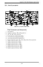
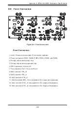
1. and 2. Optional Primary and Secondary
I
2
C Connectors
The optional I
2
C connectors are connected to
the CSE-PTJBOD-CB2 board and are used
to monitor the power supply status and to
control the fans. See the table on the right
for pin definitions.
I
2
C Connector
Pin Definitions
Pin# Definition
1
Data
2
Ground
3
Clock
4
No Connection
D-6 Front Connector and Pin Definitions
Backplane
Main Power
4-Pin Connector
Pin# Definition
1
+12V
2 and 3
Ground
4
+5V
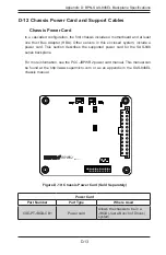
3. Backplane Main Power Connectors
The 4-pin connectors, designated PWR1,
PWR2, PWR3, PWR4, PWR5, and PWR6,
provide power to the backplane. See the
table on the right for pin definitions.
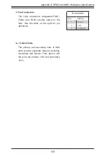
5. Primary and Secondary Expander Chips
This primary and secondary expander chips
allow the backplane to support dual ports,
cascading, and failover.
4. Primary and Secondary Flash Chips
The primary and secondary flash chips
enhance the backplane memory.
6. EPP Ports
The EPP ports are used for manufacturer
diagnostic purposes only.
Содержание SC848 Series
Страница 1: ...SC848 CHASSIS SERIES USER S MANUAL 1 0b SUPER SC848A R1K62B SC848E16 R1K62B SC848E26 R1K62B...
Страница 32: ...2 20 SC848 Chassis Notes...
Страница 38: ...SC848 Chassis Manual 3 6 Notes...
Страница 72: ...SC848 Chassis Manual 4 34 Notes...
Страница 82: ...SC848 Chassis Manual 5 10 Notes...
Страница 86: ...SC848 Chassis Manual A 4 Notes...
Страница 88: ...SC848 Chassis Manual B 2 Notes...
Страница 98: ...C 10 SC848 Chassis Manual Notes...


