


H-4
SC847 Chassis Manual
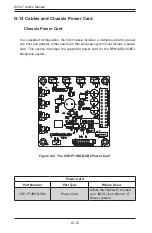
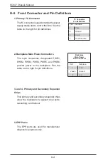
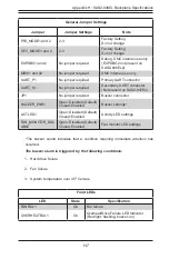
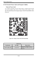
1. Primary I
2
C Connector
The I
2
C connector is used to monitor the power
supply status and to control the fans. See the
table on the right for pin definitions.
I
2
C Connector
Pin Definitions
Pin# Definition
1
Data
2
Ground
3
Clock
4
No Connection
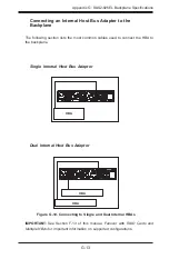
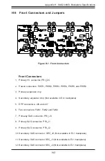
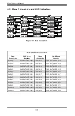
H-6 Front Connector and Pin Definitions
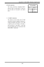
Backplane
Main Power
4-Pin Connector
Pin# Definition
1
+12V
2 and 3
Ground
4
+5V
2. Backplane Main Power Connectors
The 4-pin connectors, designated PWR1,
PWR2, PWR3, PWR4, PWR5, and PWR6,
provide power to the backplane. See the
table on the right for pin definitions.
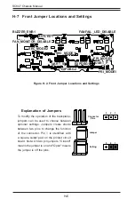
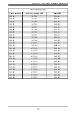
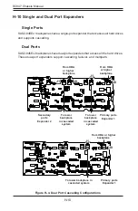
3. and 4. Primary and Secondary Expander
Chips
This primary and secondary expander chips
allow the backplane to support dual ports,
cascading, and failover.
5. EPP Ports
The EPP ports are used for manufacturer
diagnostic purposes only.
Содержание SC847 Series
Страница 12: ...SC847 Chassis Manual 1 4 Notes...
Страница 32: ...2 20 SC847 Chassis Manual Notes...
Страница 53: ...5 15 Chapter 5 Chassis Setup and Maintenance Figure 5 14 Placing the System Fan...
Страница 76: ...SC847 Chassis Manual B 2 Notes...
Страница 86: ...C 10 SC847 Chassis Manual Notes...
Страница 96: ...D 10 SC847 Chassis Manual Notes...
Страница 118: ...E 22 SC847 Chassis Manual Notes...
Страница 187: ...H 23 Appendix H SAS2 846EL Backplane Specifications Notes...