background image

C-2

 C2SBM-Q User's Manual

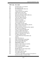
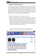
Supero Doctor III Interface Display Screen-I (Health Information)

B. Configuring 

Supero Doctor III

The  Supero  Doctor  III  program  is  a  Web-base  management  tool  that  supports 
remote management capability. It includes Remote and Local Management tools.  
The local management is called the SD III Client. The Supero Doctor III program 
included on the CDROM that came with your motherboard allows you to monitor 
the environment and operations of your system. Supero Doctor III displays crucial 
system information such as CPU temperature, system voltages and fan status. See 
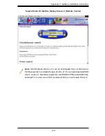
the Figure below for a display of the Supero Doctor III interface.

Note 1

: Both default user name and password are ADMIN.

Note 2: 

In the Windows OS environment, the Supero Doctor III settings take 

precedence  over  the  BIOS  settings.  When  first  installed,  Supero  Doctor  III 

adopts  the  temperature  threshold  settings  previously  set  in  the  BIOS.  Any 
subsequent changes to these thresholds must be made within Supero Doctor, 
since the SD III settings override the BIOS settings. For the Windows OS to 
adopt the BIOS temperature threshold settings, please change the SDIII set-
tings to be the same as those set in the BIOS.

Содержание C2SBM-Q

Страница 1: ...C2SBM Q USER S MANUAL Revision 1 1a...

Страница 2: ...ERING SUCH HARDWARE SOFTWARE OR DATA Any disputes arising between manufacturer and customer shall be governed by the laws of Santa Clara County in the State of California USA The State of California C...

Страница 3: ...installed and serviced by a technician Manual Organization Chapter 1 describes the features specifications and performance of the mainboard and provides detailed information about the chipset Chapter...

Страница 4: ...oring 1 10 1 5 ACPI Features 1 10 1 6 Power Supply 1 11 1 7 Versatile Media Capabilities 1 12 1 8 Super I O 1 12 Chapter 2 Installation 2 1 Static Sensitive Devices 2 1 2 2 Motherboard Installation 2...

Страница 5: ...tion of Jumpers 2 21 GLAN Enable Disable 2 21 Audio Enable 2 22 Watch Dog Enable 2 22 CPU Front Side Speed 2 23 PCI PCI Exp Slots to SMB Speeds 2 23 IDE Enable Disable 2 24 USB Wake up 2 25 2 8 Onboar...

Страница 6: ...roduction 4 1 4 2 Running Setup 4 2 4 3 Main BIOS Setup 4 2 4 4 Advanced Setup 4 7 4 5 Security Setup 4 19 4 6 TPM State 4 21 4 7 Boot Settings 4 22 4 8 Exit 4 23 Appendices Appendix A BIOS POST Messa...

Страница 7: ...ighest standards in quality and performance Please check that the following items have all been included with your mother board If anything listed here is damaged or missing contact your retailer All...

Страница 8: ...per Micro Computer B V Het Sterrenbeeld 28 5215 ML s Hertogenbosch The Netherlands Tel 31 0 73 6400390 Fax 31 0 73 6416525 Email sales supermicro nl General Information support supermicro nl Technical...

Страница 9: ...ge Note All pictures and drawings shown in this manual were based upon the latest PCB Revision available at the time of publishing of the manual The motherboard you ve received may or may not look exa...

Страница 10: ...fans may be needed for proper system cooling The C2SBM Q offers the option of overclocking however Supermicro is not responsible for any damage caused by the use of overclocking FAN1 JI2C2 JWOR JFSB3...

Страница 11: ...Port Serial Port 1 4 Connectors DIMM 1A 2A 1B 2B Memory Slots Fans 1 3 Fan 1 CPU Fan Fan 2 3 Chassis Fan Headers IDE IDE 1 Connector JF1 FP Control Panel Header JL1 Chassis Intrusion Header JLED Onbo...

Страница 12: ...x16 Slot 7 One 1 PCI Express x4 x8 physical slot 5 Two 2 32 bit PCI 33MHz Slot 4 and 6 BIOS 16 Mb Firmware SPI Phoenix BIOS Flash BIOS DMI 2 3 PCI 2 2 ACPI 1 0 2 0 SMBIOS 2 3 and Plug and Play PnP PC...

Страница 13: ...orts IT8213 ITE controller supports up to two IDE devices 11 USB 2 0 ports for a speed of up to 480Mbps Realtek ALC 883 7 1 Channel High Definition Audio HDA codecs supports 10 DAC Channels Built in G...

Страница 14: ...A775_PROCESSOR ICH 9DO LPC I O MS SER 1 2 VRM 11 0 ADDR CTRL CTRL ADDR DATA DATA LPC PCI_32 DDR2_800 667 VRM V11 0 DMI 2_PCI_x32 DIMM_CHA S ATA 300 4x SATAII CK505 CLK 1 PCIE_x16 GRAPHIC Q35 DIMM_CHB...

Страница 15: ...ortunistic refresh scheme a memory thermal management scheme and Partial Writes to Memory using Data Mask DM signals The GMCH contains one PCI Express x16 port intended for an external PCI Express gra...

Страница 16: ...sitivity of the voltage monitor by using SuperO Doctor III 1 5 ACPI Features ACPI stands for Advanced Configuration and Power Interface The ACPI specifica tion defines a flexible and abstract hardware...

Страница 17: ...ork Interface Card NIC that has WOL capability In addition an onboard LAN controller can also support WOL without any connection to the WOL header The 3 pin WOL header is to be used with a LAN add on...

Страница 18: ...feature is available when a processor that supports the virtualization of platforms is installed on the motherboard 1 8 Super I O The disk drive adapter functions of the Super I O chip include a data...

Страница 19: ...correct type of onboard CMOS battery as specified by the manu facturer Do not install the onboard battery upside down to avoid possible explo sion Unpacking The motherboard is shipped in antistatic p...

Страница 20: ...re that you install the processor into the CPU LGA 775 socket before you install the CPU heatsink 2 The Intel LGA 775 Processor package contains the CPU fan and heatsink as sembly If you buy a CPU sep...

Страница 21: ...ket Do not move the CPU horizontally or vertically Do not rub the CPU against the surface or against any pins of the socket to avoid damage to the CPU or the socket 7 With the CPU inside the socket in...

Страница 22: ...if the protective film is not removed from the heatsink 5 Apply the proper amount of thermal grease on the CPU Note if your heatsink came with a thermal pad please ignore this step 6 If necessary rea...

Страница 23: ...atsink fan wires to the CPU Fan connector 1 Unplug the power cord from the power supply 2 Disconnect the heatsink fan wires from the CPU fan header 3 Use your finger tips to gently press on the fasten...

Страница 24: ...ulating DIMM 1A DIMM 1B and or DIMM 2A DIMM 2B with memory modules of the same size and of the same type will result in dual channel two way interleaved memory that is faster than the single channel n...

Страница 25: ...ith the receptive point on the slot Notch Notch Release Tab Release Tab DIMMII To Install Insert module vertically and press down until it snaps into place Pay attention to the alignment notch at the...

Страница 26: ...ntel ICH9DO JPUSB2 J47 JPL1 COM2 W83627DHG S I O 2 J14 COM3 Slot6 PCI 33MHz PCI1 JPT1 DIMM2B LAN CTRL LAN 1 C2SBM Q COM1 J31 JBT1 2 5 Control Panel Connectors IO Ports The I O ports are color coded in...

Страница 27: ...lot7 PCI E x16 JI2C1 JP2 Intel ICH9DO JPUSB2 J47 JPL1 COM2 W83627DHG S I O 2 J14 COM3 Slot6 PCI 33MHz PCI1 JPT1 DIMM2B LAN CTRL LAN 1 C2SBM Q COM1 J31 JBT1 2 Front Control Panel JF1 contains header pi...

Страница 28: ...PCI 33MHz PCI1 JPT1 DIMM2B LAN CTRL LAN 1 C2SBM Q COM1 J31 JBT1 Power LED The Power LED connection is located on pins 15 and 16 of JF1 Refer to the table on the right for pin definitions Power LED Pin...

Страница 29: ...ndicator The NIC Network Interface Control ler LED connection for the GLAN port is located on pins 11 and 12 of JF1 Attach the NIC LED cables to display network activity Refer to the table on the righ...

Страница 30: ...Button The Reset Button connection is located on pins 3 and 4 of JF1 Attach it to a hardware reset switch on the computer case Refer to the table on the right for pin definitions Reset Button Pin Def...

Страница 31: ...1 C2SBM Q COM1 J31 JBT1 2 6 Connecting Cables ATX Auxiliary Power Connectors A 24 pin main power connector is located at J40 This power connector meet the SSI EPS 12V specification See the table on t...

Страница 32: ...s headers on the motherboard Six of them are Back Panel USB ports USB 0 1 J11 and USB 2 3 4 5 J43 The other four are headers that can be used for front panel connections USB 6 7 J44 USB 8 9 J45 and on...

Страница 33: ...JPT1 DIMM2B LAN CTRL LAN 1 C2SBM Q COM1 J31 JBT1 Fan Headers The C2SBM Q has three chassis fan head ers Fan 1 to Fan 3 Fan 1 is the CPU Fan Fan 2 to Fan 3 are system chassis fans Note Pins 1 3 of a 4...

Страница 34: ...M3 Slot6 PCI 33MHz PCI1 JPT1 DIMM2B LAN CTRL LAN 1 C2SBM Q COM1 J31 JBT1 ATX PS 2 Keyboard and PS 2 Mouse Ports The ATX PS 2 keyboard and the PS 2 mouse are located at J28 See the table on the right f...

Страница 35: ...J47 JPL1 COM2 W83627DHG S I O 2 J14 COM3 Slot6 PCI 33MHz PCI1 JPT1 DIMM2B LAN CTRL LAN 1 C2SBM Q COM1 J31 JBT1 A WOR B WOL Wake On Ring The Wake On Ring header is des ignated JWOR This function allow...

Страница 36: ...Fan3 JPUSB1 PCI3 Slot7 PCI E x16 JI2C1 JP2 Intel ICH9DO JPUSB2 J47 JPL1 COM2 W83627DHG S I O 2 J14 COM3 Slot6 PCI 33MHz PCI1 JPT1 DIMM2B LAN CTRL LAN 1 C2SBM Q COM1 J31 JBT1 A GLAN1 B Speaker Buzzer S...

Страница 37: ...Audio HDA J46 codec that provides 10DAC channels simultaneously supporting7 1soundplaybackandtwochannels of independent stereo sound output multiple streaming through the front panel stereo out for fr...

Страница 38: ...dphones are plugged in the back panel audio output is disabled This is done through the FP Audio header J12 If the front panel interfacecardisnotconnectedtothefront panel audio header jumpers should b...

Страница 39: ...or jumper settings The default setting is enabled GLAN Enable Pin Definition 1 2 Enabled default 2 3 Disabled A GLAN Port1 Enable A FAN1 JI2C2 JWOR JFSB3 JF1 JWD JLED Battery J40 DIMM1A DIMM2A DIMM1B...

Страница 40: ...J31 JBT1 A Audio Enable B Watch Dog Enable Watch Dog Enable Disable JWD controls the Watch Dog function Watch Dog is a system monitor that can reboot the system when a software application hangs Close...

Страница 41: ...3627DHG S I O 2 J14 COM3 Slot6 PCI 33MHz PCI1 JPT1 DIMM2B LAN CTRL LAN 1 C2SBM Q COM1 J31 JBT1 A JFSB1 B JFSB2 C JFSB3 D JI2 C1 E JI2 C2 CPU Front Side Bus Speed JFSB1 JFSB2 and JFSB3 allow you to set...

Страница 42: ...Intel Q35 24 pin ATX PWR Audio CTRL CD IN CD1 Front Audio W83627DHG S I O 1 IDE CTRL ITE 8213 J15 COM4 USB 10 JWOL I SATA0 I SATA1 JS4 JS3 JS1 JS2 FAN2 Fan3 JPUSB1 PCI3 Slot7 PCI E x16 JI2C1 JP2 Intel...

Страница 43: ...l lows you to wake up the system by pressing a key on the USB keyboard or by clicking the USB mouse of your system The JPUSB jumpers are used together with the USB Wake Up function in the BIOS Enable...

Страница 44: ...ink LED Rear View When viewing from the rear side of the chassis A FAN1 JI2C2 JWOR JFSB3 JF1 JWD JLED Battery J40 DIMM1A DIMM2A DIMM1B I SATA2 I SATA3 SPEAKER KB MOUSE CPU Fan J28 VGA JGS1 USB 2 3 4 5...

Страница 45: ...SB 10 JWOL I SATA0 I SATA1 JS4 JS3 JS1 JS2 FAN2 Fan3 JPUSB1 PCI3 Slot7 PCI E x16 JI2C1 JP2 Intel ICH9DO JPUSB2 J47 JPL1 COM2 W83627DHG S I O 2 J14 COM3 Slot6 PCI 33MHz PCI1 JPT1 DIMM2B LAN CTRL LAN 1...

Страница 46: ...ollowing when connecting the hard disk drive cables A red mark on a wire typically designates the location of pin 1 IDE Connector There is one IDE Connector on the C2SBM Q Be sure to close Pin 1 and P...

Страница 47: ...tsink making sure it is fully seated and connect the chassis speaker and the power LED to the motherboard Check all jumper settings as well 5 Use the correct type of onboard CMOS battery as specified...

Страница 48: ...tion 1 6 for details on recommended power supplies 2 The battery on your motherboard may be old Check to verify that it still supplies 3VDC If it does not replace it with a new one 3 If the above step...

Страница 49: ...al Ad dress Extension PAE mode behavior which improves driver compatibility For more information please read the following article at Microsoft s Knowledge Base website at http support microsoft com k...

Страница 50: ...Under the Properties tab scroll down the list of devices in the menu and check the box beside Microphone Question After I have installed 4 pieces of 1GB Memory why does the BIOS only detect about 3 14...

Страница 51: ...ently displayed on the outside of the shipping carton and mailed prepaid or hand carried Shipping and handling charges will be applied for all orders that must be mailed when service is complete For f...

Страница 52: ...3 6 C2SBM Q User s Manual Notes...

Страница 53: ...up battery pro vides power to the CMOS logic enabling it to retain system parameters Each time the computer is powered on the computer is configured with the values stored in the CMOS logic by the sys...

Страница 54: ...g Delete immediately after turning the system on or 2 When the message shown below appears briefly at the bottom of the screen during the POST Power On Self Test press the Delete key to activate the m...

Страница 55: ...ss the Enter key to save the data BIOS Date The item displays the date that the BIOS was built Hard Disk Pre Delay When enabled this featyre will add a delay to provide time needed for HDD self initia...

Страница 56: ...elect Intel to enable the Intel SATA RAID firmware Select Adaptec to use the Adaptec HostRAID firmware The options are Intel and Adaptec SATA AHCI Enable Select Enable to enable the function of Serial...

Страница 57: ...ive s type capacity number of heads etc Select User to manually enter the parameters for the storage device in stalled on this particular port For hard drives enter a number between 1 to 39 to select...

Страница 58: ...ectors 8 Sectors and 16 Sectors LBA Mode Control This item determines whether the Phoenix BIOS will access the IDE Channel 0 Master Device via the LBA mode The options are Enabled and Disabled 32 Bit...

Страница 59: ...is setting allows you to Enable or Disable the graphic logo screen display during bootup QuickBoot Mode If enabled this feature will speed up the POST Power On Self Test routine by skipping certain te...

Страница 60: ...ower Button Behavior If set to Instant Off the system will power on or power off immediately as soon as the user hits the power button The options are Instant Off and 4 second Override Resume On Modem...

Страница 61: ...the system may hang If this happens clear the CMOS to recover the system Hyperthreading Available when supported by the CPU Set to Enabled to use the Hyperthreading Technology which will result in in...

Страница 62: ...Enabled the Maximum Extended CPUID will be set to 3 The options are Disabled and Enabled Echo TPR Set to Enabled to prevent xTPR messages from being sent to the system The options are Disabled and En...

Страница 63: ...p Technology and allows the system to automatically adjust the processor voltage and core frequency in an effort to reduce power consumption and heat dissipation The options are Enabled C States GV1 G...

Страница 64: ...lows the user to configure the DVMT 4 0 Graphics Memory to be used by the Internal Graphics Device The options are Fixed DVMT and Auto Pre allocated Memory Size This feature allows the user to set the...

Страница 65: ...d up CPU operations Select Uncached to disable this function Select Write Through to allow data to be cached into the buffer and written into the system memory at the same time Select Write Protect to...

Страница 66: ...f the settings above to make changes to the following Option ROM Scan When enabled this setting will initialize the device expansion ROM The options are Enabled and Disabled Enable Master This setting...

Страница 67: ...and try again A different OS requires a different Bus Master clock rate PEG PCI Express Graphics Port Sub menu Access the submenu for each of the settings above to make changes to the following PCI Ex...

Страница 68: ...elect the clock frequency for the Keyboard Controller The options are 6MHz 8MHz 12MHz and 16MHz Serial Port A This setting allows you to decide how the system controls Serial Port A The options are En...

Страница 69: ...is setting allows you to select the base I O address for Serial Port C The options are 220 and 238 Interrupt This setting allows you to select the IRQ interrupt request for Serial Port B The options a...

Страница 70: ...the CPU is still within its normal operating state and below the CPU Temperature Tolerance The motherboard fans and CPU will run normally as configured in the BIOS The fans may adjust to a faster spee...

Страница 71: ...Fan speed triggering the Overheat Alarm etc Since CPUs can have different Tem perature Tolerances the installed CPU can now send its Temperature Toler ance to the motherboard resulting in better CPU t...

Страница 72: ...dows OS environment the Supero Doctor III settings take pre cedence over the BIOS settings When first installed Supero Doctor III adopts the temperature threshold settings previously set in the BIOS A...

Страница 73: ...password has been entered for the system User Password Is This item indicates if a user password has been entered for the system Clear means such a password has not been used and Set means a user pass...

Страница 74: ...e system at bootup The options are Enabled password required and Disabled password not required Trusted Platform Support Select Enabled to enable support for trusted platforms and allow the BIOS to au...

Страница 75: ...tate Select Clear to clear or erase all information related to TPM support If set to Clear the sub menu Physical Presence Operations will appear Select Rejecttocanceltheselection SelectExecutetoprocee...

Страница 76: ...ns for the devices included in the candidate list above are currently disabled Use a key or a key to move the device up or down Use the f key or the r key to specify the type of an USB device either f...

Страница 77: ...Discarding Changes Highlight this item and hit Enter to exit the BIOS Setup utility without saving any changes you may have made Load Setup Defaults Highlight this item and hit Enter to load the defau...

Страница 78: ...4 26 C2SBM Q User s Manual Notes...

Страница 79: ...d Keyboard controller failed test May require replacing keyboard controller Keyboard locked Unlock key switch Unlock the system to proceed Monitor type does not match CMOS Run SETUP Monitor type not c...

Страница 80: ...ST did not complete successfully POST loads default values and offers to run Setup If the failure was caused by incorrect values and they are not corrected the next boot will likely fail On systems wi...

Страница 81: ...MI Failed ServerBIOS2 test error Cannot generate software NMI Non Maskable Interrupt Fail Safe Timer NMI Failed ServerBIOS2 test error Fail Safe Timer takes too long device Address Conflict Address co...

Страница 82: ...ccessfully tested One or more I2O Block Storage Devices were excluded from the Setup Boot Menu There was not enough room in the IPL table to display all installed I2O block storage devices Operating s...

Страница 83: ...Optional message displayed during POST Can be turned off in Setup PS 2 Mouse PS 2 mouse identified Run the I2O Configuration Utility One or more unclaimed block storage devices have the Configuration...

Страница 84: ...A 6 C2SBM Q User s Manual Notes...

Страница 85: ...ore doing so BIOS will write the error to port 80h attempt to initialize video and write the Appendix B BIOS POST Codes POST Code Description 02h Verify Real Mode 03h Disable Non Maskable Interrupt NM...

Страница 86: ...hadow system BIOS ROM 3Ah Auto size cache 3Ch Advanced configuration of chipset registers 3Dh Load alternate registers with CMOS values 41h Initialize extended memory for RomPilot optional 42h Initial...

Страница 87: ...nd IRQs optional 81h Late POST device initialization 82h Detect and install external RS232 ports 83h Configure non MCD IDE controllers 84h Detect and install external parallel ports 85h Initialize PC...

Страница 88: ...epare to boot operating system B4h 1 One short beep before boot B5h Terminate QuietBoot optional B6h Check password optional B7h Initialize ACPI BIOS and PPM Structures B9h Prepare Boot BAh Initialize...

Страница 89: ...ialize Memory size EEh Shadow Boot Block EFh System memory test F0h Initialize interrupt vectors F1h Initialize Run Time Clock F2h Initialize video F3h Initialize System Management Manager F4h Output...

Страница 90: ...B 6 C2SBM Q User s Manual Notes...

Страница 91: ...ng each item you must re boot the system before proceeding with the next item on the list The bottom icon with a CD on it allows you to view the entire contents of the CD Appendix C Software Installat...

Страница 92: ...ays crucial system information such as CPU temperature system voltages and fan status See the Figure below for a display of the Supero Doctor III interface Note 1 Both default user name and password a...

Страница 93: ...e Control Note SD III Software Revision 1 0 can be downloaded from our Web site at ftp ftp supermicro com utility Supero_Doctor_III You can also download SDIII User s Guide at http www supermicro com...

Страница 94: ...C 4 C2SBM Q User s Manual Notes...

Страница 95: ...ted to result in significant injury or loss of life or catastrophic property damage Accordingly Supermicro disclaims any and all liability and should buyer use or sell such products for use in such ul...

Отзывы: