


11
Chapter 1: Introduction
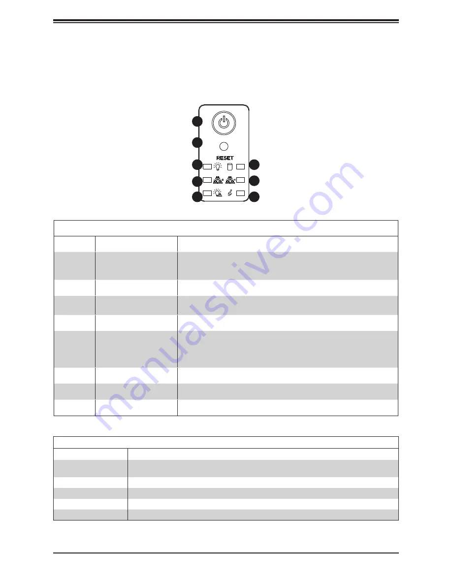
Figure 1-2. Control Panel View
1
8
7
6
5
4
3
2
Control Panel Features
The switches and LEDs located on the control panel are described below. See Chapter 4 for
details on the control panel connections.
Control Panel Features
Item
Feature
Description
1
Power Button
The main power switch applies or removes primary power from the power
supply to the server but maintains standby power. To perform most maintenance
tasks, unplug the system to remove all power.
2
Reset Button
The reset button is used to reboot the system.
3
Power LED
Indicates power is being supplied to the system power supply units. This LED
should normally be illuminated when the system is operating.
4
NIC2 LED
Indicates network activity on LAN2 when flashing.
5
Power Fail LED
Indicates a power supply module has failed. The second power supply module
will take the load and keep the system running but the failed module will need
to be replaced. When this LED turns solid red or blinks red, check the AC
source. This LED should be off when the system is operating normally.
6
Information LED
Alerts operator of several states, as noted in the table below.
7
NIC1 LED
Indicates network activity on LAN1 when flashing.
8
HDD LED
Indicates activity on a hard drive when flashing.
Information LED
Status
Description
Continuously on and red
An overheat condition has occurred.
(This may be caused by cable congestion.)
Blinking red (1Hz)
Fan failure, check for an inoperative fan.
Blinking red (0.25Hz)
Power failure, check for a non-operational power supply.
Solid blue
UID has been activated locally to locate the server in a rack environment.
Blinking blue
UID has been activated using IPMI to locate the server in a rack environment.


