background image


C236AX USER MANUAL 

 
Part Number:  C23AX  

Содержание C236AX

Страница 1: ... C236AX USER MANUAL Part Number C23AX ...

Страница 2: ...9 Form Factor and Dimensions 9 Environmental Requirements 10 CHAPTER 2 HARDWARE CONFIGURATION 11 Handling Precautions 11 Jumper Locations 12 Header Locations 13 Connector Locations 14 Setting the Jumpers 17 Jumpers 18 Headers 20 Connectors 33 Installing Memory 39 Installing CPU 40 Installing HEAT SINK FAN 41 Installing FAN s 41 Installing Power Cables 41 Back Panel Connections 42 CHAPTER 3 AMIBIOS...

Страница 3: ...ENDIX B FLASH BIOS PROGRAMMING 67 How to Reflash the BIOS 67 APPENDIX C EFI BIOS AND POST CODES 68 Checkpoint Ranges 68 Standard Checkpoints 69 APPENDIX D SATA INTERFACES 77 RAID 0 77 RAID 1 77 RAID 10 78 RAID 5 78 Loading the Intel Rapid Storage Technology RAID Driver 79 APPENDIX E TERMINOLOGY 80 ...

Страница 4: ... use or misuse of this publication This publication and any accompanying software may not in whole or in part be copied photocopied translated or reduced to any machine readable form without prior consent from the vendor manufacturer or creators of this publication except for copies kept by the user for backup purposes Brand and product names mentioned in this publication may or may not be copyrig...

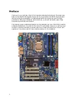
Страница 5: ...formance With proper installation and maintenance your board will provide years of high performance and trouble free operation This manual provides a detailed explanation into the installation and use of the C23AX industrial embedded motherboard It is written for the novice PC user installer However as with any major computer component installation previous experience is helpful and should you not...

Страница 6: ...erence when the equipment is operated in a commercial environment This equipment generates uses and can radiate radio frequency energy and if not installed and used in accordance with the instruction manual may cause harmful interference to radio communications Operation of this equipment in a residential area is likely to cause harmful interference in which case the user will be required to corre...

Страница 7: ...y support Embedded Processor 1151 LGA package Intel Xeon E3 1275 v5 3 60GHz 4 core 8 threads 8M cache 80W Intel Xeon E3 1225 v5 3 30GHz 4 core 4 threads 8M cache 80W Non Embedded Processors For additional supported processors please contact your Sales Representative Chipset GL82C236 PCH Four DDR4 2133MHz DIMM sockets Up to 64GB of ECC memory Intel Integrated Graphics One HDMI port at 3840x2160 30H...

Страница 8: ...I UEFI BIOS 128Mb SPI Embedded I 0 Serial Ports 6 6 full handshake RS232 serial ports COM2 configurable to RS 232C RS 422 and RS485 USB Interfaces 12 4 USB3 0 ports on back I O blue 2 USB3 0 ports on 2x10 20 pin header 2 USB2 0 ports on back I O black 2 USB2 0 ports on 2x5 10 pin headers 1 USB2 0 port on 1x5 pin header 1 USB2 0 port connector Keyboard Mouse Header Combined PS 2 Keyboard and mouse ...

Страница 9: ...ithium battery or equivalent Watchdog Timer Reset 1 65535 sec min and 1 min step Expansion 1x PCI Express x16 Slot 1x PCI Express x4 Slot 1x PCI Express x1 Slot 4x PCI 32bit Slots 1x mSATA connector 1x SIM card slot 1x M 2 2230 slot Power connectors 24 pin ATX power connector compatible with 20 pin connector 8 pin 12V power connector Fan Headers CPUFAN 4 pin header PWM SYSFAN1 4 pin header compati...

Страница 10: ...10 Environmental Requirements RoHS compliant assembly CATEGORY OPERATING NON OPERATING TEMPERATURE 0 C to 60 C 40 C to 70 C HUMIDITY 0 to 90 non condensing 5 to 95 40 C non condensing ...

Страница 11: ...ain installation procedures such as forcing the system board into the chassis or placing too much torque on a mounting screw Take special care when installing or removing the system memory DIMMs Never force a memory into a socket Screwdrivers slipping off a screw and scraping the board can break a trace or component leads rendering the board unusable Always handle the C23AX with care Static Warnin...

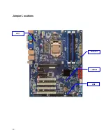
Страница 12: ...12 Jumper Locations JRI1 JCMOS1 JRI2 JATATX1 ...

Страница 13: ...13 Header Locations JKBMS1 JCOM5 JAUXP1 SYSFAN1 JCOM6 CPUFAN1 JCOM4 JAUDIO1 JCOM3 JCOM2A JBAT1 JCOM2B JFP1 JGSPIO1 JSMB1 JSPDIF1 JSPI1 JSPK1 JUSB1 JUSB2 JUSB4 JLPC1 LPT1 SYSFAN2 JGPIO1 ...

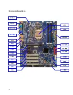
Страница 14: ...14 Connector Locations ATX12V1 JSIM1 JUSB3 ATXPWR1 PCI1 PCIE3 PCIE2 PCIE1 PCI2 PCI3 PCI4 AUDIO1 LAN1 LAN2 VGA1 DP1 COM1 HDMI PSUSB1 NGFF1 MPCIE1 CPU1 DIMMs SATA2 1 SATA4 3 SATA6 5 ...

Страница 15: ...rt 2 RS 422 RS 485 header 3x2 header pitch 2 00mm JCOM3 COM4 COM5 COM6 Serial Port headers 5x2 header pitch 2 54mm JDIO1 GPIO header 5x2 header pitch 2 54mm JFP1 Front Panel header 5x2 header pitch 2 54mm JKBMS1 PS 2 Keyboard Mouse header 6x1 wafer pitch 2 54mm JSGPIO SGPIO header 3x2 header pitch 2 00mm JSMB1 SMBUS header 5x1 header pitch 2 54mm JSPDIF1 S PDIF header 4x1 header pitch 2 54mm JSPI1...

Страница 16: ...HDMI1 HDMI connector JUSB3 USB2 0 Single USB A JSIM1 SIM card slot LAN1 NIC1 stacked with dual USB3 0 Stacked RJ 45 LAN2 NIC2 stacked with dual USB3 0 Stacked RJ 45 MPCIE1 Full Half size miniPCIe connector NGFF1 M 2 module slot M 2 2230 PCIE1 PCI Express x16 PCIE2 PCI Express x1 PCIE3 PCI Express x4 PCI1 32bit PCI slots PCI2 32bit PCI slots PCI3 32bit PCI slots PCI4 32bit PCI slots PSUSB1 PS 2 Key...

Страница 17: ...unt covers the pins B Three or four pin jumpers are used for multiple selections Instructions for these jumpers will indicate which two pins to cover For example for JP1 2 3 the shunt will be covering pins 2 and 3 leaving pin 1 exposed How to identify pin number 1 on Figure Looking to the solder side The board side with fewer components of the PCB Printed Circuit Board pin number 1 will have a squ...

Страница 18: ...S 1 2 Normal 1 3 1 3 2 3 ATX 1 2 AT 1 3 1 3 Jumpers Use the diagram below and the tables on the following pages to locate and set the on board configuration jumpers JATATX1 AT ATX Power Mode Selection JCMOS1 Clear CMOS ...

Страница 19: ...19 JRI1 COM1 RI Function Selection 3 4 closed 5V 1 1 2 closed RI 1 1 5 6 closed 12V JRI2 COM2 RI Function Selection 3 4 closed 5V 1 2 closed RI 5 6 closed 12V ...

Страница 20: ... to locate the headers CPUFAN1 Processor Fan header PWM PIN ASSIGNMENT 4 1 4 PWM 3 Tachometer 2 12V 1 GND JAUDIO1 Front Panel AUDIO header PIN ASSIGNMENT PIN ASSIGNMENT 9 1 10 2 1 MIC L 2 GND 3 MIC R 4 ACZ_DET 5 LINE OUT R 6 MIC_Sense 7 NC 8 Key 9 LINE OUT L 10 LINE_Sense ...

Страница 21: ...NMENT 1 5V 2 NC 3 NC 4 SMB_CLK 5 CASEOPEN 6 NC 7 GND 8 GND 9 ERROR_LED 10 SMB_DATA 11 ERROR_LED 12 5V 13 LAN1_ACT 14 LAN1_LINK100 15 GND 16 LAN1_LINK1000 17 LAN2_ACT 18 LAN2_LINK100 19 GND 20 LAN2_LINK1000 JBAT1 External Battery PIN ASSIGNMENT 1 2 1 BAT 2 GND ...

Страница 22: ...eader PIN ASSIGNMENT PIN ASSIGNMENT 9 1 10 2 1 DCD TX 2 RX 3 TX 4 DTR 5 GND 6 DSR 7 RTS 8 CTS 9 RI 10 KEY JCOM2B Serial Port 2RS 422 RS 485 header PIN ASSIGNMENT PIN ASSIGNMENT 1 2 5 6 1 485TX 2 422RX 3 485TX 4 422RX 5 5V 6 GND ...

Страница 23: ...eader PIN ASSIGNMENT PIN ASSIGNMENT 9 1 10 2 1 DCD 2 RX 3 TX 4 DTR 5 GND 6 DSR 7 RTS 8 CTS 9 RI 10 KEY JCOM4 Serial Port 4 header PIN ASSIGNMENT PIN ASSIGNMENT 9 1 10 2 1 DCD 2 RX 3 TX 4 DTR 5 GND 6 DSR 7 RTS 8 CTS 9 RI 10 KEY ...

Страница 24: ...eader PIN ASSIGNMENT PIN ASSIGNMENT 9 1 10 2 1 DCD 2 RX 3 TX 4 DTR 5 GND 6 DSR 7 RTS 8 CTS 9 RI 10 KEY JCOM6 Serial Port 6 header PIN ASSIGNMENT PIN ASSIGNMENT 9 1 10 2 1 DCD 2 RX 3 TX 4 DTR 5 GND 6 DSR 7 RTS 8 CTS 9 RI 10 KEY ...

Страница 25: ... 11 12 1 DI0 2 DO0 3 DI1 4 DO1 5 DI2 6 DO2 7 DI3 8 DO3 9 SMB_CLK_9555 10 SMB_DATA_9555 11 GND 12 5VStby JFP1 Front Panel header PIN ASSIGNMENT PIN ASSIGNMENT 1 2 9 10 1 HDD LED 2 Power LED 3 HDD LED 4 Power LED 5 Reset SW 6 Power SW 7 GND 8 GND 9 NC 10 KEY ...

Страница 26: ...1 PS 2 Keyboard Mouse header PIN ASSIGNMENT 1 6 MSCLK 5 VCC 4 GND 3 MSDATA 2 KBDATA 1 KBCLK JSGPIO SGPIO header PIN ASSIGNMENT PIN ASSIGNMENT 1 2 5 6 1 GND 2 GND 3 SGIO_LOAD 4 SGIO_DOUT0 5 SGIO_CLK 6 SGIO_DOUT1 ...

Страница 27: ...27 JSMB1 SMBUS header PIN ASSIGNMENT 1 1 SMBUS_CLK 2 SMBUS_DATA 3 SMBUS_ALERT 4 GND 5 VCC3 JSPDIF1 SPDIF header PIN ASSIGNMENT 1 4 1 5V 2 KEY 3 SPDIF 4 GND ...

Страница 28: ...28 JSPI1 SPI header PIN ASSIGNMENT PIN ASSIGNMENT 7 1 8 2 1 3 3V 2 GND 3 SSPI_CS0 _R 4 SSPI_SCLK_R 5 SSPI_SO_R 6 SSPI_SI_R 7 SSPI_HOLD 0 8 KEY JSPK1 Speaker header PIN ASSIGNMENT 1 1 5V 2 NC 3 NC 4 SPK ...

Страница 29: ...T PIN ASSIGNMENT 10 11 1 20 10 NC 11 D2 9 D1 12 D2 8 D1 13 GND 7 GND 14 SSTX2 6 SSTX1 15 SSTX2_ 5 SSTX1 16 GND 4 GND 17 SSRX2 3 SSRX1 18 GND 2 SSRX1 19 VBUS2 1 VBUS 20 KEY JUSB2 USB 2 0 header PIN ASSIGNMENT 1 5 1 VCC 2 D 3 D 4 GND 5 GND ...

Страница 30: ...NT PIN ASSIGNMENT 2 10 1 9 1 VCC 2 VCC 3 D 4 D 5 D 6 D 7 GND 8 GND 9 KEY 10 NC JLPC1 LPC header PIN ASSIGNMENT PIN ASSIGNMENT 2 10 1 9 1 LPC_AD0 2 3 3V 3 LPC_AD1 4 BUF_PLT_RST 5 LPC_AD2 6 LPC_FRAME 7 LPC_AD3 8 LPC_CLK 9 LPC_SERIRQ 10 GND ...

Страница 31: ...1 26 2 1 STB 2 AFD 3 PD0 4 ERR 5 PD1 6 INIT 7 PD2 8 SLIN 9 PD3 10 GND 11 PD4 12 GND 13 PD5 14 GND 15 PD6 16 GND 17 PD7 18 GND 19 ACK 20 GND 21 BUSY 22 GND 23 PE 24 GND 25 SLCT 26 KEY SYSFAN1 System Fan 1 header PWM PIN ASSIGNMENT 4 1 4 PWM 3 Tachometer 2 12V 1 GND ...

Страница 32: ...32 SYSFAN2 System Fan 2 header PIN ASSIGNMENT 3 1 1 GND 2 12V 3 Tachometer ...

Страница 33: ...33 Connectors ATXPWR1 ATX Power Connector Connect the power supply to the 24 pin ATX Power Connector ATX12V1 ATX 12V Connector ...

Страница 34: ...34 CPU1 Processor Socket DIMMs ...

Страница 35: ...35 JUSB3 Internal USB2 0 Connector JSIM1 SIM Card Slot MPCIE1 Full Half size mini PCIe Connector ...

Страница 36: ...36 NGFF1 M 2 Module Slot PCIE1 PCIE2 PCIE3 ...

Страница 37: ...37 PCI1 PCI2 PCI3 PCI4 ...

Страница 38: ...38 SATA2 and 1 SATAIII 6Gb s connectors SATA4 and 3 SATAIII 6Gb s connector SATA6 and 5 SATAIII 6Gb s connector ...

Страница 39: ... Firmly press the modules into the socket until it snaps into place To take full advantage of the dual channel functionality please install memories in pairs populating the blue memory sockets first Adding memory modules to the C23AX is only allowed for specific configurations Contact your Sales representative to confirm your configuration Unreliable and incorrect operation may occur Any issues en...

Страница 40: ... processor make sure to carefully follow these instructions Push the lever down unclip and lift it Open the load plate Remove the plastic cover Carefully align processor with notches on the socket Close the load plate close and latch the lever ...

Страница 41: ... the board Installing FAN s The CPUFAN header can control fans up to 0 75A while the SYSFAN headers support fans of up to 1 5A and can be configured for 3 pin or 4 pin operation Connect the fan s plug to CPUFAN and or SYSFAN taking into consideration the polarity of connector 3 pin FAN s will not be controllable when connected to the 4 pin CPUFAN header and will be on at full speed Connect the fan...

Страница 42: ...Mouse Connector B COM1 Connector DB9M C VGA Connector D LAN2 and USB3 0 Stacked RJ45 and USB3 0 E LAN1 and USB3 0 Stacked RJ45 and USB3 0 F AUDIO Stack Line in Speaker and Microphone Audio stack G USB2 0 Connectors H HDMI Connector I DisplayPort Connector DP1 ...

Страница 43: ...vailable to display error messages should a critical error be encountered therefore POST uses beeps on the speaker to indicate the failure of a critical system component during this time Consult Appendix B for a list of Beep codes used by the BIOS BIOS Boot Sequence Although you can select the device boot order in the BIOS setup there are situations were booting from an alternate device may be req...

Страница 44: ... white Often a text message will accompany it The CMOS BIOS setup utility uses a key based navigation system called hot keys Most of the setup utility hot keys can be used at any time during the setup navigation process These keys include F1 F10 Enter ESC Arrow keys and so on Note There is a hot key legend located in the right frame on most setup screens HOT KEY DESCRIPTION Left Right The Left and...

Страница 45: ...y It is not displayed on the key legend by default To set the Fail Safe settings of the BIOS press the F8 key on your keyboard It is located on the upper row of a standard 101 keyboard The Fail Safe settings allow the motherboard to boot up with the least amount of options set This can lessen the probability of conflicting settings ...

Страница 46: ... any changes you have made and exit the Setup Press the Esc key to exit the setup without saving your changes The following screen will appear Press the Enter key to discard changes and exit You can also use the Arrow key to select Cancel and then press the Enter key to abort this function and return to the previous screen Enter The Enter key allows you to display or change the setup option listed...

Страница 47: ... between fields The date must be entered in MM DD YY format The time is entered in HH MM SS format Note The time is in 24 hour format For example 5 30 A M appears as 05 30 00 and 5 30 P M as 17 30 00 BIOS SETUP UTILITY Main Advanced Chipset Security Boot Save Exit BIOS Information BIOS Vendor American Megatrends Core Version UEFI 2 4 PI 1 3 Build Date and Time 04 14 2016 18 00 00 Access Level Admi...

Страница 48: ...CT6106D HW Monitor S5 RTC Wake Settings Serial Port Console Redirection CPU Configuration Intel TXT Information SATA Configuration Network Stack Configuration CSM Configuration USB Configuration Select Screen Select Item Enter Select Change Opt F1 General Help F2 Previous Values F3 Optimized Defaults F4 Save Exit ESC Exit Version 2 17 1255 Copyright 2016 American Megatrends Inc ...

Страница 49: ...WR Fail Always On Always Off or Keep Last State Watch Dog timer Disabled or set time Wake Up by Ring Enabled or Disabled USB Power state in S3 S5 Enabled or Disabled AMT Configuration Intel AMT Enabled or Disabled Un Configure ME Enabled or Disabled PCH FW Configuration ME FW Version 11 0 0 1202 ME Firmware Mode Normal Mode ME Firmware Type Full SKU Firmware ME Firmware SKU Corporate SKU PTT Capab...

Страница 50: ...s Auto UART 232 422 485 RS232 RS422 or RS485 Serial Port 3 Configuration Serial Port Disabled or Enabled Device Settings IO 3E8h IRQ 7 Change Settings Auto Serial Port 4 Configuration Serial Port Disabled or Enabled Device Settings IO 2E8h IRQ 10 Change Settings Auto Serial Port 5 Configuration Serial Port Disabled or Enabled Device Settings IO 200h IRQ 5 Change Settings Auto Serial Port 6 Configu...

Страница 51: ...l Port Console Redirection COM1 or SOL Console Redirection Disabled or Enabled Console Redirection Settings Terminal Type VT100 VT100 VT UTF8 or ANSI Bits per second 9600 19200 38400 57600 or 115200 Data Bits 7 or 8 Parity None Even Odd Mark or Space Stop Bits 1 or 2 Flow Control None or Hardware RTS CTS VT UTF8 Combo Key Support Disabled or Enabled Recorder Mode Disabled or Enabled Resolution 100...

Страница 52: ...y Supported 64 bit Supported EIST Technology Supported CPU C3 state Supported CPU C6 state Supported CPU C7 state Supported CPU C8 state Supported CPU C9 state Not Supported CPU C10 state Not Supported L1 Data Cache 32 KB x 4 L1 Code Cache 32 KB x 4 L2 Cache 256 KB x 4 L3 Cache 8 MB L4 Cache Not Present Hyper threading Enabled or Disable Active Processor Cores All 1 2 or 3 Intel Virtualization Tec...

Страница 53: ...ode None Major code None Minor code None SATA Configuration SATA Controller s Enabled or Disabled SATA Mode Selection AHCI or RAID Mode Software Feature Mask Config Serial ATA Port0 through 5 Empty or HDD model Software Preserve Unknown or SUPPORTED SATA Port Enabled or Disabled SATA Device Type Hard Disk or Solid State Topology Flex Software Feature Mask Config HDD Unlock Enabled or Disabled LED ...

Страница 54: ... Option ROM Messages Force BIOS or Keep Current INT19 Trap Response Immediate or Postponed Boot option filter Legacy only or UEFI only Option ROM execution Network Do Not Launch UEFI or Legacy Storage Do Not Launch UEFI or Legacy Video Do Not Launch UEFI or Legacy Other PCI Device Do Not Launch UEFI or Legacy USB Configuration USB Configuration USB Module Version 14 USB Controllers 1 XHCI USB Devi...

Страница 55: ...55 USB hardware delays and time outs USB transfer time out 1 5 10 or 20 sec Device reset time out 10 20 30 or 40 sec Device power up delay Auto or Manual If set to Manual allows to set a fixed time ...

Страница 56: ... Save Exit System Agent SA Configuration PCH IO Configuration North Bridge Parameters Select Screen Select Item Enter Select Change Opt F1 General Help F2 Previous Values F3 Optimized Defaults F4 Save Reset ESC Exit Version 2 17 1255 Copyright 2016 American Megatrends Inc ...

Страница 57: ...ntrol Graphics Configuration IGFX VBIOS 1036 Skip Scanning of External Gfx Card Enabled or Disabled Primary Display Auto IGFX PEG or PCIE Internal Graphics Auto Disabled or Enabled DMI OPI Configuration DMI X4 GEN3 PEG Port Configuration PCI E x16 Slot Not Present Enable Root Port Auto Disabled or Enabled Max Link Speed Auto GEN1 GEN2 or GEN3 Detect Non Compliance Device Enabled or Disabled Progra...

Страница 58: ...Q Mode Continuous or Quiet PCI Express Configuration PCI E Root Port 1 PCIe x4 Slot PCI E Root Port 5 mPCIe mSATA Slot PCI E Root Port 6 PCIe to PCI Bridge PCI E Root Port 7 PCIe x1 Slot PCI E Root Port 8 Intel I211AT LAN Chip PCI E Root Port 9 NGFF1 M 2 Slot lane 1 PCI E Root Port 10 NGFF1 M 2 Slot lane 2 PCI E Root Port 12 LAN For each port selections are PCIe Port Enabled or Disabled ASPM Suppo...

Страница 59: ...59 HD Audio Configuration HD Audio HD Audio Auto Enabled or Disabled Amplifier Gain 20dB 26dB 32dB or 36dB ...

Страница 60: ...r when entering Setup If ONLY the User s password is set then this is a power on password and must be entered to boot or enter Setup In Setup the User will have Administrator rights The password length must be in the following range Minimum length 3 Maximum length 20 Secure Boot Menu System mode Setup Secure Boot Not Active Vendor Keys Not Active Secure Boot Disabled or Enabled Secure Boot Mode St...

Страница 61: ...iet Boot Disabled Boot Option Priorities Boot Option 1 Fast Boot Disabled New Boot Option Policy Default CD DVD ROM Drive BBS Priorities Hard Drive BBS Priorities Select Screen Select Item Enter Select Change Opt F1 General Help F2 Previous Values F3 Optimized Defaults F4 Save Exit ESC Exit Version 2 17 1255 Copyright 2016 American Megatrends Inc ...

Страница 62: ...e NUM LOCK on boot On or Off Quiet Boot Enable or Disable Boot Option Priorities Boot Option 1 Select first boot device Boot Option 2 Select second boot device CD DVD Drive BBS Priorities If you have more than one CD DVD select the primary Hard Drive BBS Priorities If you have more than one HDD select the primary ...

Страница 63: ...s and Reset Discard Changes and Reset Default Options Restore Defaults Boot Override P0 PLEXTOR DVDR PX 880SA P1 ST980817SM Select Screen Select Item Enter Select Change Opt F1 General Help F2 Previous Values F3 Optimized Defaults F4 Save Exit ESC Exit Version 2 17 1255 Copyright 2016 American Megatrends Inc ...

Страница 64: ... RAM Typically the address space that is allocated for PCI add in cards PCI Express configuration space BIOS and chipset overhead resides above the top of RAM On a system that has 64GB of memory installed it is not possible to use all of the installed memory due to system address space being allocated for other system critical functions These functions include BIOS SPI Flash device 128Mb Local API...

Страница 65: ...terrupt 3 8 Communications Port COM2 4 9 Communications Port COM1 5 6 6 11 Floppy Disk Controller 7 7 8 N A System CMOS Real Time Clock 9 10 ACPI Mode when enabled 10 3 Available 11 2 Available 12 4 PS 2 Compatible Mouse Port 13 N A Numeric Data Processor 14 5 Prim SATA Channel 15 1 Sec SATA Channel 16 23 APIC only ...

Страница 66: ...line comprising of the following stages Vertex Fetch Vertex Shader Hull Shader Tesselation Domain Shader Geometry Shader Rasterizer Pixel Shader Pixel Output The Direct X 12 API is supported at feature level 12_1 Media Support Intel Quicksync Clear Video Technology HD GEN 9 implements multiple media video codecs in hardware as well as a rich set of image processing algorithms All supported media c...

Страница 67: ...the necessary files for the upgrade You will also need a bootable device like a floppy USB or hard drive loaded with DOS Windows tools are available upon request How to Reflash the BIOS Boot from DOS and execute the batch file provided by technical support Wait for a message telling you that the process completed properly Reboot load Optimized Defaults and Save ...

Страница 68: ...Pre EFI Initialization PEI equivalent to the Bootblock on the AMIBIOS Driver Execution Environment DXE equivalent to the POST in AMIBIOS Boot Device Selection BDS system setup pre OS user interface and selecting a bootable device Checkpoint Ranges Status Code Range Description 0x01 0x0B SEC Execution 0x0C 0x0F SEC Errors 0x10 0x2F PEI Execution up to and including memory detection 0x30 0x4F PEI Ex...

Страница 69: ...lization after microcode loading 0x09 Southbridge initialization after microcode loading 0x0A OEM initialization after microcode loading 0x0B Cache initialization SEC Error Codes 0x0C 0x0D Reserved for future AMI SEC error codes 0x0E Microcode not found 0x0F Microcode not loaded SEC Beep Codes NONE PEI Phase Status Code Description Progress Codes 0x10 PEI Core is started 0x11 Pre memory CPU initia...

Страница 70: ...ion other 0x30 Reserved for ASL see ASL Status Codes below 0x31 Memory Installed 0x32 CPU post memory initialization is started 0x33 CPU post memory initialization Cache initialization 0x34 CPU post memory initialization Application Processor s AP initialization 0x35 CPU post memory initialization Boot Strap Processor BSP selection 0x36 CPU post memory initialization System Management Mode SMM ini...

Страница 71: ...5B Reset PPI is not available 0x5C 0x5F Reserved for future AMI error codes S3 Resume Progress Codes 0xE0 S3 Resume is started S3 Resume PPI is called by the DXE IPL 0xE1 S3 Boot script execution 0xE2 Video repost 0xE3 OS S3 wake vector call 0xE4 0xE7 Reserved for future AMI progress codes S3 Resume Error Codes 0xE8 S3 Resume failed 0xE9 S3 Resume PPI not found 0xEA S3 Resume Boot script error 0xE...

Страница 72: ...PI is not available DXE Phase Status Code Description 0x60 DXE Core is started 0x61 NVRAM initialization 0x62 Installation of the Southbridge Runtime services 0x63 CPU DXE initialization is started 0x64 CPU DXE initialization CPU Module specific 0x65 CPU DXE initialization CPU Module specific 0x66 CPU DXE initialization CPU Module specific 0x67 CPU DXE initialization CPU Module specific 0x68 PCI h...

Страница 73: ...pecific 0x77 Southbridge DXE initialization SB module specific 0x78 ACPI module initialization 0x79 CSM initialization 0x7A 0x7F Reserved for future AMI DXE codes 0x80 0x8F OEM DXE initialization codes 0x90 Boot Device Selection BDS phase is started 0x91 Driver connecting is started 0x92 PCI bus initialization is started 0x93 PCI bus Hot Plug Controller initialization 0x94 PCI Bus enumeration 0x95...

Страница 74: ...AP end 0xB2 Legacy option ROM initialization 0xB3 System reset 0xB4 USB hot plug 0xB5 PCI bus hot plug 0xB6 Clean up of NVRAM 0xB7 Configuration reset 0xB8 0xBF Reserved for future AMI codes 0xC0 0xCF OEM BDS initialization codes DXE Error Codes 0xD0 CPU initialization error 0xD1 Northbridge initialization error 0xD2 Southbridge initialization error 0xD3 Some of the Architectural Protocols are not...

Страница 75: ...ce requirements can t be met ACPI ASL Checkpoints Status Code Description 0x01 System is entering S1 sleep state 0x02 System is entering S2 sleep state 0x03 System is entering S3 sleep state 0x04 System is entering S4 sleep state 0x05 System is entering S5 sleep state 0x10 System is waking up from S1 sleep state 0x20 System is waking up from S2 sleep state 0x30 System is waking up from S3 sleep st...

Страница 76: ...EC initialization before microcode loading 0x0A OEM SEC initialization after microcode loading 0x1D 0x2A OEM pre memory initialization codes 0x3F 0x4E OEM PEI post memory initialization codes 0x80 0x8F OEM DXE initialization codes 0xC0 0xCF OEM BDS initialization codes ...

Страница 77: ...rmance but does not deliver fault tolerance If one drive fails then all data in the array is lost This RAID configuration is also known as a Striped set This RAID array can read and write data in parallel from multiple drives This is what makes this RAID level one of the fastest RAID 1 RAID 1 Mirroring and Duplexing Provides disk mirroring Data is written identically between disks This RAID config...

Страница 78: ... single drive failure Upon drive failure any subsequent reads can be calculated from the distributed parity such that the drive failure is masked from the end user The array will have data loss in the event of a second drive failure and is vulnerable until the data that was on the failed drive is rebuilt onto a replacement drive A single drive failure in the set will result in reduced performance ...

Страница 79: ...653212 1 8TB Member Disk 0 Loading the Intel Rapid Storage Technology RAID Driver 1 Begin Windows Setup by booting from the Windows Installation CD 2 At the beginning of Windows Setup press F6 to install third party SCSI or RAID driver When prompted insert the diskette with the Intel Rapid Storage Driver These drivers are available on you Driver CD and need to be copied to a floppy disk Note a USB...

Страница 80: ...r though it can also be used to carry audio USB and other forms of data DMA Direct Memory Access DRAM Dynamic Random Access Memory DVMT Dynamic Video Memory Technology GMCH Graphic Memory Controller Hub EFI UEFI The Unified Extensible Firmware Interface BIOS is a specification that defines a software interface between an operating system and platform firmware UEFI is a replacement for the older BI...

Страница 81: ...MN C23AX 01 ...

Отзывы: