Supermicro SuperServer 510P-M Скачать руководство пользователя страница 18

18

Chapter 1: Introduction

Connector

Description

JSEN1

System Front Intel Temperature Sensor Header

JSTBY1

Standby Power Header

JTPM1

Trusted Platform Module/Port 80 Connector

NVMe0~5

PCIe 4.0 x8 Slimline SAS Connectors (NVMe4~9 for -NTF only)

S-SATA0, S-SATA1

SATA 3.0 Ports with SATA DOM Power

UID

Unit Identifier (UID) and BMC Reset Button

LAN1, LAN2

LAN 1G Base-T Ports (Intel I350 controller)

USB0/1

Back Panel Universal Serial Bus (USB) 3.2 Ports

USB2/3, USB4/5

Front Access USB 3.2 Headers

USB6/7

Back Panel USB 3.2 Gen 1 Ports

USB8/9

Front Accessible USB 3.2 Gen 1 Header

USB10

USB 3.2 Gen 1 Type-A Header

VGA

VGA Port

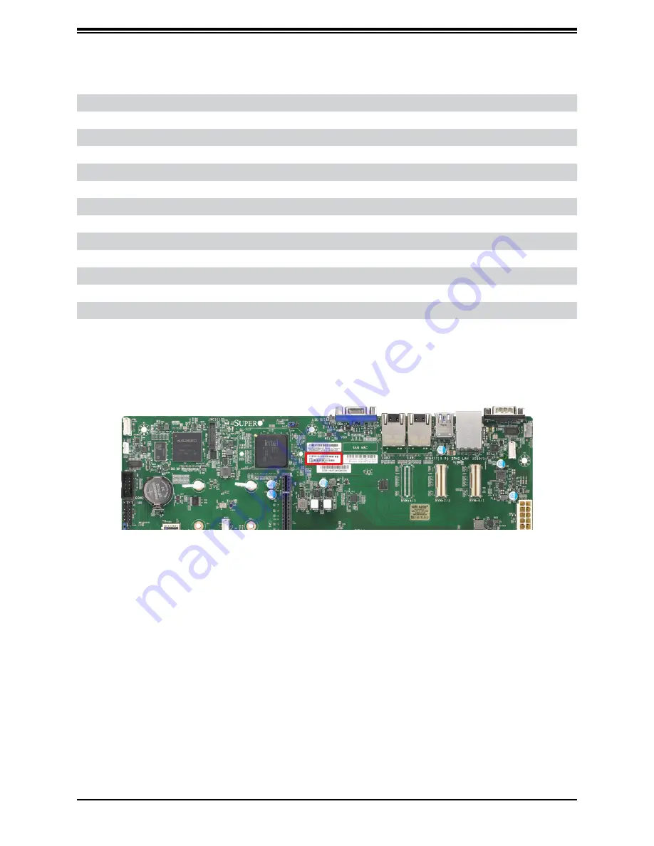
Figure 1-7. Location of BMC Password

Содержание SuperServer 510P-M

Страница 1: ...USER S MANUAL Revision 1 0 SuperServer 510P M 510P MR...

Страница 2: ...Class A device or in residential environment for Class B device This equipment generates uses and can radiate radio frequency energy and if not installed and used in accordance with the manufacturer...

Страница 3: ...s and utilities https www supermicro com wdl Product safety info http www supermicro com about policies safety_information cfm If you have any questions please contact our support team at support supe...

Страница 4: ...apter 2 Server Installation 2 1 Overview 19 2 2 Unpacking the System 19 2 3 Preparing for Setup 19 Choosing a Setup Location 19 Rack Precautions 20 Server Precautions 20 Rack Mounting Considerations 2...

Страница 5: ...Removing the Processor Carrier Assembly from the PHM 37 Removing the Processor from the Carrier Assembly 38 3 5 Memory Support and Installation 39 Memory Support 39 General Guidelines for Optimizing M...

Страница 6: ...stallation 72 5 3 SuperDoctor 5 73 5 4 IPMI 74 BMC ADMIN User Password 74 Chapter 6 Optional Components 6 1 Optional Parts List 75 6 2 Power Supply Modules 75 6 3 3 5 to 2 5 Drive Trays 76 Enabling NV...

Страница 7: ...tional BIOS POST Codes 84 7 5 Crash Dump Using IPMI 85 7 6 CMOS Clear 86 7 7 Where to Get Replacement Components 87 7 8 Reporting an Issue 87 Technical Support Procedures 87 Returning Merchandise for...

Страница 8: ...er B V Het Sterrenbeeld 28 5215 ML s Hertogenbosch The Netherlands Tel 31 0 73 6400390 Fax 31 0 73 6416525 Email sales supermicro nl General Information support supermicro nl Technical Support rma sup...

Страница 9: ...ots support up to 2048GB of ECC RDIMM LRDIMM LRDIMM 3DS with speeds up to 3200MHz Drive Support Four hot swap 3 5 drive bays Two SATADOMs Expansion Slots One PCIe 4 0 x16 slot 6 Two M 2 PCIe 3 0 x4 SA...

Страница 10: ...low For OS RAID or non RAID configurations some LED indications are not supported such as hot spare For VROC configurations refer to the VROC appendix in this manual Drive Carrier LED Indicators Color...

Страница 11: ...when flashing NIC LAN1 LED Indicates network activity on LAN1 when flashing NIC LAN2 LED Indicates network activity on LAN2 when flashing Power LED Indicates a power supply module has failed Informat...

Страница 12: ...0P M one power supply module 510P MR two redundant power supply modules PWS1 on the left PWS2 on the right LAN Ports Two 1GBaseT LAN ports see Section 1 1 Overview for details USB Two USB3 2 Gen 1 por...

Страница 13: ...Fan Fail OTP UVP OFF Amber LED Power Supply Warning Events Where the power supply continues to operate High temperature Over voltage under voltage etc OFF 1Hz Blink Amber AC present only 12vsb on PS o...

Страница 14: ...slots Processor Single 3rd Generation Intel Xeon Scalable processor System fans Four 4cm heavy duty fans two fans shown on left are optional 1 3 System Architecture This section covers the locations...

Страница 15: ...TPM HEADER Rear 2 Front 4 10 NVMe NTF 4 NVMe F NCSI CONN SYSTEM POWER 7 1 PHASE 220W VR13 HC 5 PCI E X8 Gen4 SLIM SAS 10 NVME PCI E X8 Gen2 DMI 0 1B 3 NCSI master 2 LAN RGRMII FRONT PANEL CTRL FAN SPE...

Страница 16: ...JPL1 UID VGA LAN2 LAN1 USB6 7 3 0 IPMI_LAN USB0 1 COM1 FAN5 JSEN1 NVMe4 5 NVMe2 3 NVMe0 1 JPWR1 JPWR2 JPI2C1 NVMe6 7 I SATA0 3 I SATA0 3 DIMMG1 DIMMF1 DIMMH1 DIMME1 DIMMA1 DIMMC1 DIMMD1 DIMMB1 CPU SLO...

Страница 17: ...oard CMOS Battery COM1 COM2 COM Port COM Header via header FAN1 FAN5 FANA FANB CPU System Fan Headers IPMI_LAN Dedicated IPMI 2 0 LAN Port I SATA0 I SATA7 Intel PCH SATA 3 0 Ports with RAID 0 1 5 10 S...

Страница 18: ...9 for NTF only S SATA0 S SATA1 SATA 3 0 Ports with SATA DOM Power UID Unit Identifier UID and BMC Reset Button LAN1 LAN2 LAN 1G Base T Ports Intel I350 controller USB0 1 Back Panel Universal Serial Bu...

Страница 19: ...e server It should be situated in a clean dust free area that is well ventilated Avoid areas where heat electrical noise and electromagnetic fields are generated It will also require a grounded AC pow...

Страница 20: ...y precautions in Appendix A Determine the placement of each component in the rack before you install the rails Install the heaviest server components at the bottom of the rack first and then work your...

Страница 21: ...f should be grounded Particular attention should be given to power supply connections other than the direct connections to the branch circuit i e the use of power strips etc To prevent bodily injury w...

Страница 22: ...you want to place the 510P M MR in the rack see Rack and Server Precautions in Section 2 2 Position the chassis rail guides at the desired location in the rack keeping the sliding rail guide facing t...

Страница 23: ...azard The rack stabilizing mechanism must be in place or the rack must be bolted to the floor before you slide the unit out for servicing Failure to stabilize the rack can cause the rack to tip over N...

Страница 24: ...s on either side of the chassis four total 1 First determine how far the server will extend out the front of the rack Larger chassis should be positioned to balance the weight between front and back I...

Страница 25: ...Please follow the procedures given in each section 3 1 Removing Power Use the following procedure to ensure that power has been removed from the system This step is necessary when removing or installi...

Страница 26: ...hich allows easy access to the inside of the chassis Removing the Top Cover 1 Disconnect the chassis from any power source if necessary see above 2 Remove any screws securing the cover to the chassis...

Страница 27: ...Use a grounded wrist strap designed to prevent static discharge Touch a grounded metal object before removing any PCB printed circuit board from its antistatic bag Handle PCBs by their edges only do...

Страница 28: ...unplug the AC power cords from all power supplies Check that the plastic protective cover is on the CPU socket and that none of the socket pins are bent If they are contact your retailer When handling...

Страница 29: ...tic Sensitive Devices section earlier in this chapter 1 Hold the processor with the gold pins LGA lands facing down Locate the gold triangle at the corner of the processor and the corresponding hollow...

Страница 30: ...ess the other end down until it snaps into latch 2 6 After the processor is placed inside the carrier examine the four sides of the processor making sure that the processor is properly seated on the c...

Страница 31: ...the heatsink over with the thermal grease facing up Note the two triangle cutouts A B located at the diagonal corners of the heatsink as shown in the drawing below 2 On the processor carrier assembly...

Страница 32: ...cket for Installation The CPU socket comes with a plastic protective cover which needs to be removed before installing the Processor Heatsink Module PHM Do this by gently squeezing the grip tabs then...

Страница 33: ...nd Component Installation Installing the PHM into the CPU Socket 1 Remove the plastic protective cover from the CPU socket Gently squeeze the grip tabs then pull the cover off CPU Socket with Plastic...

Страница 34: ...asteners a b c d on the CPU socket 3 Locate four PEEK nuts A B C D and four rotating wires 1 2 3 4 on the heatsink as shown below 4 Check that the rotating wires 1 2 3 4 are in the unlatched position...

Страница 35: ...sink on the CPU socket making sure that each nut is properly aligned with its corresponding threaded fastener Latched State Top View 7 Press all four rotating wires outward to latch the PHM onto the C...

Страница 36: ...CPU Socket Be sure the system is shut down and all AC power cords are unplugged 1 Use a t30 bit screwdriver to loosen the four PEEK nuts on the heatsink in the sequence of A B C and D 2 Press the four...

Страница 37: ...r Carrier Assembly from the PHM Detach the four plastic clips a b c d on the processor carrier assembly from the four corners of the heatsink A B C D as shown below and lift off the processor carrier...

Страница 38: ...the Carrier Assembly Unlock the lever from its locked position and push it upwards to disengage the processor from the carrier as shown below right Carefully remove the processor from the carrier Proc...

Страница 39: ...er Channel DPC Data below assumes 2 SPC unless otherwise noted 1DPC 2DPC 8 Gb 16 Gb 1 2V 1 2V RDIMM SRx8 8 GB 16 GB 3200 2933 PTH 3200 SMT SRx4 16 GB 32 GB DRx8 16 GB 32 GB DRx4 32GB 64 GB RDIMM 3DS 4...

Страница 40: ...C1 NVMe6 7 I SATA0 3 I SATA0 3 DIMMG1 DIMMF1 DIMMH1 DIMME1 DIMMA1 DIMMC1 DIMMD1 DIMMB1 CPU SLOT6 PCe 4 0 X16 FAN2 FAN1 JPWR3 BMC_HB_LED POWER_LED MH5 MH6 MH7 MH1 MH11 MH10 MH12 MH13 JNVI2C1 LED_CATERR...

Страница 41: ...ush both ends of the module straight down into the slot until the module snaps into place Notches Push both ends straight down into the memory slot DIMM Removal Press both release tabs on the ends of...

Страница 42: ...the motherboard Replacing the Battery Begin by removing power from the system 1 Push aside the small clamp that covers the edge of the battery When the battery is released lift it out of the holder 2...

Страница 43: ...ers For information on recommended HDDs visit the Supermicro website product pages at https www supermicro com products nfo Ultra cfm Installing Drives Removing a Hot Swap Drive Carrier from the Chass...

Страница 44: ...ving a Drive Carrier Release Button Figure 3 5 Mounting a Drive in a Carrier Removing a Drive from a Drive Carrier 1 Remove the screws that secure the hard drive to the carrier and separate the hard d...

Страница 45: ...two LED indicators an activity indicator and a status indicator For RAID configurations using a controller the meaning of the status indicator is described in the table below For OS RAID or non RAID c...

Страница 46: ...ed then turns off The Activity LED turns blue Figure 3 6 IPMI Screenshot Installing M 2 Solid State Drives The X12SPO F has two M 2 slots M 2 was formerly known as Next Generation Form Factor NGFF and...

Страница 47: ...er is running to determine which fan requires changing Never run the server for an extended period of time with the chassis open 2 Power down the system as described in Section 3 1 3 Next remove the t...

Страница 48: ...ud 1 Lay the chassis on a flat stable surface and remove the chassis cover 2 If necessary move any cables that interfere with the air shroud placement 3 Place the air shroud in the chassis The air shr...

Страница 49: ...49 Chapter 3 Maintenance and Component Installation Figure 3 8 Installing the Air Shroud Figure 3 9 Air Shroud Installed...

Страница 50: ...y been pre installed into the motherboard Perform the following steps to install an add on card Before following the procedure below to install expansion cards first turn off and remove power from the...

Страница 51: ...de and pull the system straight out until it locks you will hear a click 2 Next remove the top chassis cover 3 Disconnect the power cables that connect the power supply to the motherboard and the back...

Страница 52: ...le without powering down the system Removing the Power Supply 1 Release the retention screws that secure the chassis to the rack then grasp the two handles on either side and pull the system straight...

Страница 53: ...the system When disconnecting cables to add or replace components refer to this diagram when adding or replacing components so you can reroute them in the same manner Proper cable routing is important...

Страница 54: ...e LED blinks at 2 Hz The BMC resets and the reset duration is 250 ms Then the BMC starts to boot Restore factory default configuration Hold the button for twelve seconds The LED blinks at 4 Hz while d...

Страница 55: ...as described below 24 pin Power Supply Connector The 24 pin power supply connector JPWR1 is power input for the CPU that must be connected to the power supply You must also connect the 8 pin JPWR2 and...

Страница 56: ...ion 4 pin Power Pin Definitions Pin Definition 1 2 Ground 3 4 P12V 12V Power 4 Pin Power Connector JPWR3 is an 4 pin 12V DC power input for the CPU that must be connected to the power supply Refer to...

Страница 57: ...Power Header The Standby Power header is located at JSTBY1 on the motherboard You must have a card with a Standby Power connector and a cable to use this feature Refer to the table below for pin defin...

Страница 58: ...to the table below for pin definitions Power SMB Header Pin Definitions Pin Definition 1 Clock 2 Data 3 PMBUS_Alert 4 Ground 5 3 3V Chassis Intrusion A Chassis Intrusion header is located at JL1 on th...

Страница 59: ...an add on card to provide the out of band sideband connection between the onboard Baseboard Management Controller BMC and a Network Interface Controller NIC For the network sideband interface to work...

Страница 60: ...s of the control panel buttons and LED indicators All JF1 wires have been bundled into a single cable to simplify this connection Make sure the red wire plugs into pin 1 as marked on the motherboard T...

Страница 61: ...initions OH Fan Fail Indicator Status State Definition Off Normal On Overheat Flashing Fan Fail OH Fan Fail LED Pin Definitions JF1 Pin Definition 7 UID LED 8 OH Fan Fail LED Power Fail LED The Power...

Страница 62: ...F1 Pins Definition 13 UID_SW 14 HDD Active Power LED The Power LED connection is located on pins 15 and 16 of JF1 Refer to the table below for pin definitions Power LED Pin Definitions JF1 Pins Defini...

Страница 63: ...ocated on the motherboard The UID switch is located at JUIDB which is next to the VGA port on the back panel The UID LED is located next to the switch When you press the UID switch the UID LED will be...

Страница 64: ...Back Panel USB 6 7 3 2 Gen 1 Pin Definitions Pin Definition Pin Definition A1 VBUS B1 Power A2 D B2 USB_N A3 D B3 USB_P A4 GND B4 GND A5 Stda_SSRX B5 USB3_RN A6 Stda_SSRX B6 USB3_RP A7 GND B7 GND A8 S...

Страница 65: ...ely removed Connector Pins Jumper Setting 3 2 1 3 2 1 CMOS Clear JBT1 is used to clear CMOS which will also clear any passwords Instead of pins this jumper consists of contact pads to prevent accident...

Страница 66: ...g Jumper Settings Jumper Setting Definition Pins 1 2 Reset Default Pins 2 3 NMI Open Disabled ME Select Jumper Settings Jumper Setting Definition Pins 1 2 Normal Default Pins 2 3 Manufacturer Mode Man...

Страница 67: ...Mode 4 5 LED Indicators LAN LEDs Two LAN ports LAN1 and LAN2 are located on the I O back panel of the motherboard Each Ethernet LAN port has two LEDs The green LED indicates activity while the other...

Страница 68: ...ht Amber Blinking Active BMC Heartbeat LED A BMC Heartbeat LED is located at LEDBMC on the motherboard When LEDBMC is blinking the BMC is functioning normally Refer to the table below for more informa...

Страница 69: ...ion there are also two S SATA ports S SATA0 S SATA1 that include SATA DOM power M 2 Slot The X12SPO F motherboard has two M 2 slots M 2 was formerly known as Next Generation Form Factor NGFF and serve...

Страница 70: ...upermicro com support manuals Installing the OS 1 Create a method to access the MS Windows installation ISO file That might be a DVD perhaps using an external USB SATA DVD drive or a USB flash drive o...

Страница 71: ...iver browse the USB flash drive for the proper driver files For RAID choose the SATA sSATA RAID driver indicated then choose the storage drive on which you want to install it For non RAID choose the S...

Страница 72: ...red Another option is to go to the Supermicro website at http www supermicro com Find the product page for your motherboard and Download the Latest Drivers and Utilities Insert the flash drive or disk...

Страница 73: ...Network Management Protocol SNMP SuperDoctor 5 comes in local and remote management versions and can be used with Nagios to maximize your system monitoring needs With SuperDoctor 5 Management Server...

Страница 74: ...ules There are several BIOS settings that are related to IPMI For general documentation and information on IPMI visit our website at http www supermicro com products nfo IPMI cfm BMC ADMIN User Passwo...

Страница 75: ...4 STR 64cm 85 OHM cable CBL 1264 85 1 Gen 4 hot swap 3 5 to 2 5 HDD tray MCP 220 00043 0N 4 Gen 5 5 NVMe 3 5 to 2 5 HDD tray orange tab MCP 220 00138 0B 4 600W power supply w 48V DC input 12V and 5Vsb...

Страница 76: ...irements section on a previous page 2 Reboot the server 3 Press DEL key to enter BIOS 4 Switch to Advanced Chipset Configuration North Bridge IIO Configuration Intel VMD Technology 5 Enable the VMD ac...

Страница 77: ...er VMD controller Figure 6 2 Created Volume with enabling RAID spanned over VMD controller 12 Select specific disks for RAID with an X RAID0 Select at least two 2 24 disks RAID1 Select only two disks...

Страница 78: ...y be required in some cases Related Information Links 1 https kb vmware com s article 2151404 2 https docs vmware com en VMware vSphere 6 5 com vmware vsphere storage doc GUID 1B56EF97 F60E 4F21 82A7...

Страница 79: ...s manuals BIOS BMC drivers etc FAQs RMA warranty and other service extensions Direct Links for the 510P M MR System SYS 510P M MR specifications page X12SPO F motherboard page for links to the Quick R...

Страница 80: ...mentation and information on IPMI please visit our website at http www supermicro com products nfo IPMI cfm Figure 7 2 IPMI Sample General Memory Configuration Guide X12 IPMI User Guide SuperDoctor5 L...

Страница 81: ...MMF1 DIMMH1 DIMME1 DIMMA1 DIMMC1 DIMMD1 DIMMB1 CPU SLOT6 PCe 4 0 X16 FAN2 POWER_LED MH5 MH6 MH7 MH11 MH10 MH12 MH13 JNVI2C1 LED_CATERR MH8 CPU JPME2 PWRLED 3 Make sure that the power connector is conn...

Страница 82: ...ommended that you use the same memory type and speed for all DIMMs in the system See Section 3 3 for memory details 3 Check for bad DIMM modules or slots by swapping modules between slots and noting t...

Страница 83: ...before or during OS installation check the following 1 Source of installation Make sure that the devices used for installation are working properly including boot devices such as CD 2 Cable connectio...

Страница 84: ...nding beep codes encountered by users BIOS Error Beep POST Codes Beep Code Error Message Description 1 short Refresh Circuits have been reset Ready to power up 5 short 1 long Memory error No memory de...

Страница 85: ...u can download a crash dump of status information using IPMI The IPMI manual is available at https www supermicro com solutions IPMI cfm Check IPMI Error Log 1 Access the IPMI web interface 2 Click th...

Страница 86: ...n the system completely 2 Remove the cover of the chassis to access the motherboard 3 Remove the onboard battery from the motherboard 4 Short the CMOS pads with a metal object such as a small screwdri...

Страница 87: ...boot block code 3 If you still cannot resolve the problem include the following information when contacting us for technical support System motherboard and chassis model numbers and PCB revision numbe...

Страница 88: ...ure due to the alteration misuse abuse or improper maintenance of products During the warranty period contact your distributor first for any product problems Vendor Support Filing System For issues re...

Страница 89: ...om Europe Address Super Micro Computer B V Het Sterrenbeeld 28 5215 ML s Hertogenbosch The Netherlands Tel 31 0 73 6400390 Fax 31 0 73 6416525 Email sales supermicro nl General Information support sup...

Страница 90: ...sistance Only certified technicians should attempt to install or configure components Read this appendix in its entirety before installing or configuring components in the Supermicro chassis These war...

Страница 91: ...idere los riesgos de la corriente el ctrica y familiar cese con los procedimientos est ndar de prevenci n de accidentes Al final de cada advertencia encontrar el n mero que le ayudar a encontrar el te...

Страница 92: ...ient u zich bewust te zijn van de bij een elektrische installatie betrokken risico s en dient u op de hoogte te zijn van de standaard procedures om ongelukken te voorkomen Gebruik de nummers aan het e...

Страница 93: ...n Attention Avant de brancher le syst me sur la source d alimentation consulter les directives d installation Circuit Breaker Waarschuwing Raadpleeg de installatie instructies voordat u het systeem o...

Страница 94: ...el edificio Aseg rese de que el dispositivo de protecci n no sea superior a 250 V 20 A Attention Pour ce qui est de la protection contre les courts circuits surtension ce produit d pend de l installat...

Страница 95: ...a y del cable el ctrico quitado de los m dulos de fuente de alimentaci n antes de tener acceso el interior del chasis para instalar o para quitar componentes de sistema Attention Le syst me doit tre...

Страница 96: ...aangesloten op de voeding en van de behuizing te verwijderen Equipment Installation Warning Only trained and qualified personnel should be allowed to install replace or service this equipment Warnung...

Страница 97: ...Il est vivement recommand de confier l installation le remplacement et la maintenance de ces quipements des personnels qualifi s et exp riment s Warning This unit is intended for installation in rest...

Страница 98: ...a de estas reas mediante la utilizaci n de una herramienta especial cerradura con llave u otro medio de seguridad Attention Cet appareil doit tre install e dans des zones d acc s r serv s L acc s une...

Страница 99: ...e ou quivalent recommand e par le fabricant Jeter les piles usag es conform ment aux instructions du fabricant Advertencia Existe peligro de explosi n si la bater a se reemplaza de manera incorrecta R...

Страница 100: ...evolen wordt Gebruikte batterijen dienen overeenkomstig fabrieksvoorschriften afgevoerd te worden Redundant Power Supplies Warning This unit might have more than one power supply connection All connec...

Страница 101: ...te maken Advertencia Puede que esta unidad tenga m s de una conexi n para fuentes de alimentaci n Para cortar por completo el suministro de energ a deben desconectarse todas las conexiones Attention C...

Страница 102: ...tencia Cuando el sistema est en funcionamiento el voltaje del plano trasero es peligroso Tenga cuidado cuando lo revise Attention Lorsque le syst me est en fonctionnement des tensions lectriques circu...

Страница 103: ...con las normas de electricidad locales y nacionales Backplane Waarschuwing Een gevaarlijke spanning of energie is aanwezig op de backplane wanneer het systeem in gebruik is Voorzichtigheid is geboden...

Страница 104: ...elektriciteitsvoorschriften Warnung Die Entsorgung dieses Produkts sollte gem allen Bestimmungen und Gesetzen des Landes erfolgen Warning Ultimate disposal of this product should be handled according...

Страница 105: ...lage de ce produit sont g n ralement soumis des lois et ou directives de respect de l environnement Renseignez vous aupr s de l organisme comp tent Hot Swap Fan Warning Warning Hazardous moving parts...

Страница 106: ...rnilladores y todos los objetos lejos de las aberturas del ventilador Attention Pieces mobiles dangereuses Se tenir a l ecart des lames du ventilateur Il est possible que les ventilateurs soient toujo...

Страница 107: ...r CAS zertifizierten Kabeln mit UL CSA gekennzeichnet an Ger ten oder Produkten die nicht mit Supermicro gekennzeichnet sind AC AC UL CSA UL CSA Supermicro Supermicro UL CSA UL CSA Supermicro UL CSA U...

Страница 108: ...code pour tous les autres appareils lectriques sauf les produits d sign s par Supermicro seulement AC AC UL CSA UL CSA Supermicro UL CSA UL CSA Supermicro Advertencia Cuando instale el producto utilic...

Страница 109: ...uitmethode deze moet altijd voldoen aan de lokale voorschriften en veiligheidsnormen inclusief de juiste kabeldikte en stekker Het gebruik van niet geschikte Kabels en of Adapters kan een storing of b...

Страница 110: ...ated IPMI port One VGA port One serial COM port Two USB3 2 Gen 1 ports and two USB2 0 ports Motherboard X12SPO F 12 L x 10 W 304 8mm x 254mm Chassis 510P M CSE 813MF2TQC 505CB 510P MR CSE 813MF2TQC R4...

Страница 111: ...EN 61000 4 5 BS EN 61000 4 6 BS EN 61000 4 8 BS EN 61000 4 11 Product Safety 2014 35 EU LVD Directive UL CSA 62368 1 USA and Canada Electrical Equipment Safety Regulations 2016 IEC BS EN 62368 1 Envi...

Отзывы: