SUPER SC942 Chassis User's Guide
2-4
D. Removing Components from and Installing
Devices into the 5.25" Drive Bays
After removing the side cover from the chassis, you can remove or install
devices into the drive bays (See Section A for removing the side cover).
P r o c e d u r e s
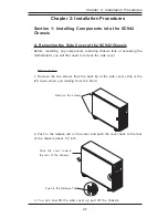
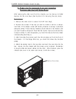
1. Remove the side cover to access the 5.25" drive bays.
2. Remove the screws of the bay you wish to install or remove a compo-
nent from. (*The chassis comes with dummy modules in all bays to maintain
adequate airflow. These dummy modules should remain in the chassis until
you want to add a component. Note that the top two bays are combined into
a single module. To add components, you must first remove the four screws
corresponding both bays.)
3. After removing the screws, push the drive module out from the front of
the chassis. For the floppy drive bay, you must first remove the two face
plates.
4. Attach the dummy rails to the new drive and insert the new drive into the
bay. Secure it to the chassis with the screws you've removed. Remember
to plug the data and power cables into the drive. When finished, place the
chassis side cover to its place and secure it with the screws.
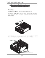
Remove the screws


