E-4
SC826 Chassis Manual
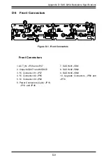
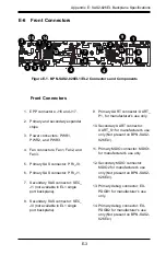
E-7 Front Connector and Settings
1. EPP Ports
The EPP ports are used for manufacturer di-
agnostic purposes only.
Backplane
Main Power
4-Pin Connector
Pin# Definition
1
+12V
2 and 3
Ground
4
+5V
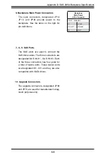
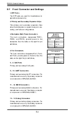
3. Backplane Main Power Connectors
The 4-pin connectors, designated PWR1,
PWR2, and PWR3, provide power to the
backplane. See the table on the right for pin
definitions.
4. Fan Connectors
The 3-pin connectors, designated Fan1, Fan2,
and Fan3, provide power to the fans. See the
table on the right for pin definitions.
Fan Connectors
Pin# Definition
1
Ground
2
+12V
3
Tachometer
2. Primary and Secondary Expander Chips
This primary and secondary expander chips
allow the backplane to support dual port, cas-
cading, and failover configurations.
5. - 8. SAS Ports
Primary and secondary SAS ports.
9. - 10. UART Connectors
Primary and secondary UART connectors: For
manufacturer's use only. Secondary connector
is not present on BPN-SAS2-826EL1.
11. - 12. MDIO Connectors
Primary and secondary MDIO connectors. For
manufacturer's use only. Secondary connector
is not present on BPN-SAS2-826EL1.
13. - 14. Debug Connectors
Primary and secondary debug connectors. For
manufacturer's use only. Secondary connector
is not present on BPN-SAS2-826EL1.
Содержание SC826 Series
Страница 12: ...SC826 Chassis Manual 1 6 Notes ...
Страница 56: ...SC826 Chassis Manual 4 18 Figure 4 16 Placing the System Fan in the Chassis 3 5 ...
Страница 60: ...SC826 Chassis Manual 4 22 Notes ...
Страница 72: ...SC826 Chassis Manual A 4 Notes ...
Страница 84: ...C 10 SC826 Chassis Manual Notes ...
Страница 94: ...D 10 SC826 Chassis Manual Notes ...
Страница 134: ...F 18 SC826 Chassis Manual Notes ...
Страница 145: ...G 11 Appendix G Cascading Configurations Notes ...


