33
Chapter 3: Component Installation and Maintenance
DIMM Installation
Verify that power has been removed from the system as described in Section 3.1.
1. Insert DIMM modules in the following order: DIMMA1, DIMMD1, DIMMB1, DIMME1,
DIMMC1, DIMMF1, DIMMA2, DIMMD2. For the system to work properly, use memory
modules of the same type and speed.
2. Push the release tabs outwards on both ends of the DIMM slot to unlock it.
3. Align the key of the DIMM module with the receptive point on the memory slot.
4. Align the notches on both ends of the module against the receptive points on the ends
of the slot.
5.
Seat the module firmly into the slot, pushing down with your thumbs evenly on both
sides of the module until it snaps into place.
6. Press the release tabs to the lock positions to secure the DIMM module into the slot.
DIMM Removal
Reverse the steps above to remove the DIMM modules from the motherboard.
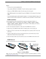
Release Tabs
Notches
Press both notches
straight down into
the memory slot.
Figure 3-3. Installing DIMMs
Note:
Visit the product page on the Supermicro website for possible updates to memory
support (
www.supermicro.com
).
Notes:
•
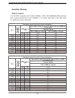
The blue slots must be populated first.
•
Only populate DIMMA2 and DIMMD2 if the extra memory support is needed.
•
Always use DDR4 DIMM modules of the same type, size and speed.
•
Mixed DIMM speeds can be installed. However, all DIMMs run at the speed of the slowest
DIMM.
•
The motherboard supports odd-numbered modules (1 or 3 modules installed). However, to
achieve the best memory performance, a balanced memory population is recommended.

