29
Chapter 3: Component Installation and Maintenance
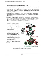
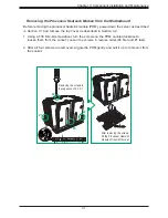
Assembling the Processor Package
Attach the processor to the narrow processor clip to create the processor package.
Caution:
Exercise extreme caution when handling the CPU. Do not touch the underside of
the CPU to avoid damaging it. Wear ESD gloves when handling components.
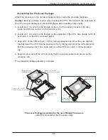
1. Locate pin 1 (A), which is the triangle on the top of the narrow processor clip. Also
locate notch B and notch C on the processor clip.
2. Locate pin 1 (A), which is the triangle on the underside of the CPU. Also, locate notch B
and notch C on the CPU as shown below.
3. Align pin 1 of the CPU with pin 1 of the narrow processor clip. Once they are aligned,
carefully insert the CPU into the processor clip by sliding notch B of the CPU into notch
B of the processor clip. Then, slide notch C of the CPU into notch C of the processor
clip.
4. Examine all corners of the CPU to verify that it is properly seated and secure on the
processor clip.
The processor package assembly is created.
A
B
C
Allow Notch C to
latch on to CPU
Allow Notch B to
latch on to CPU
A
A
B
B
C
C
Pin 1
Align CPU Pin 1
CPU (Upside Down)
w/CPU LGA Lands up
CPU/Heatsink Package
(Upside Down)
Align Notch C of the CPU
and Notch C of the Processor Clip
Align Notch B of the CPU
and Notch B of the Processor Clip
Processor Package Assembly for the non-F Model Processors
(with CPU mounted on the Processor Clip)

