background image

SuperiorFireplaces.us.com

127008-01_H

15

FINISHING FIREPLACE

Combustible materials, such as wallboard, sheet rock, drywall, plywood, 

etc. may make direct contact with sides and top around the fireplace 

face. It is important that combustible materials do not overlap the face 

itself. Brick, glass, tile or other noncombustible materials may overlap 

the front face provided they do not obstruct essential openings like 

louvered slots or any other opening. When overlapping with a noncom-

bustible facing material, use only noncombustible mortar or adhesive.

VENTING INSTALLATION 

Continued

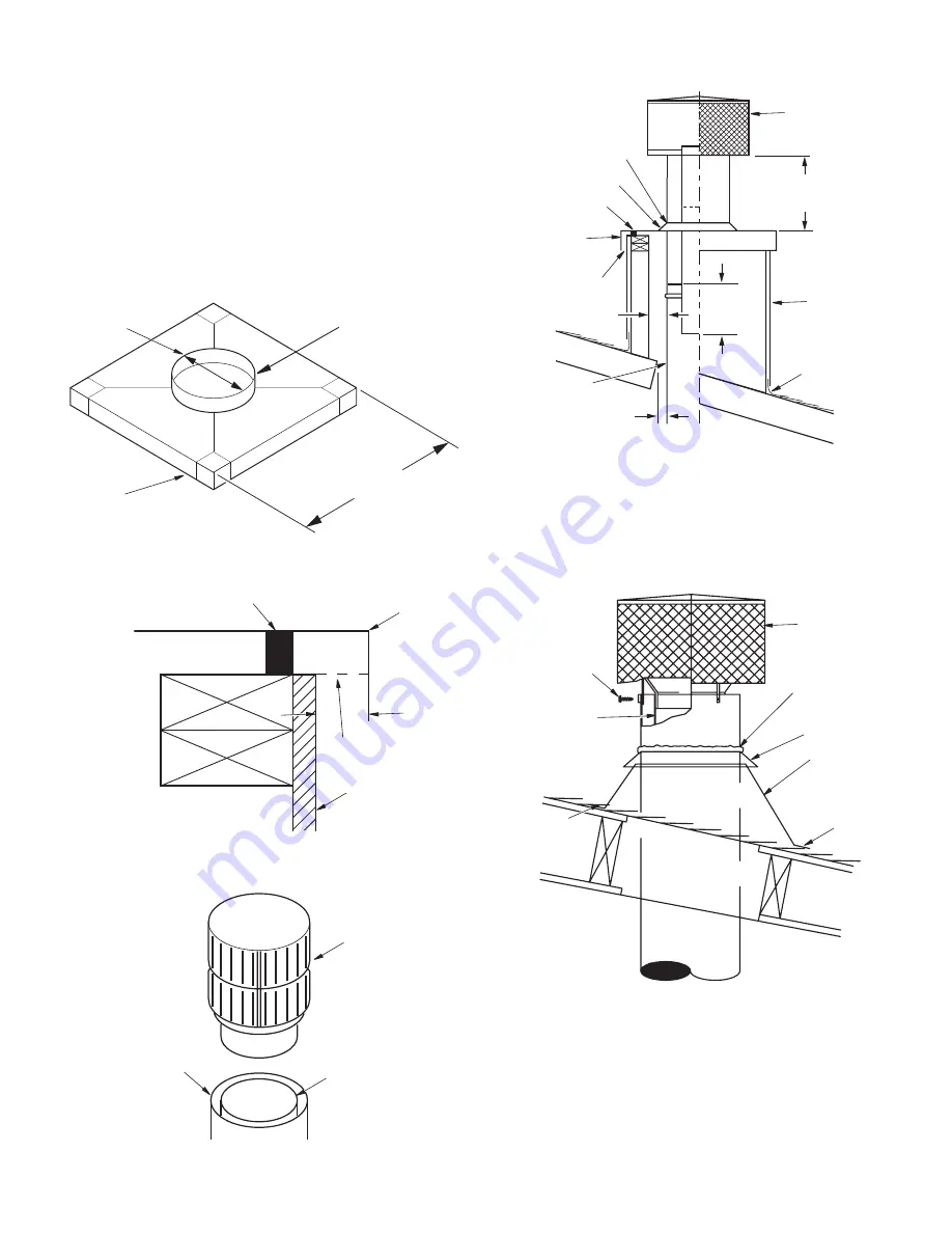
4.  Attach noncombustible spacers at each corner and place flashing 

over chase (see Figure 27). Secure flashing through sides with 

8-penny nails or sheet rock screws.

5.  Place termination cap over opening. Slip stainless steel inner 

pipe of termination into inner stainless steel chimney section 

(see Figure 28). Place galvanized steel over chimney outlet (see 

Figure 29).

6.  Attach storm collar where chimney pierces opening in flash-

ing. Caulk where storm collar touches outer chimney pipe (see 

Figure 29).

Figure 26 - Constructing Chase Top Flashing

As Required

2" Collar

16-1/2" Diameter

28 Gauge

Galvanized Steel

Figure 27 - Chase Top Flashing

Figure 28- Installing Termination Cap

1" Noncombustible Spacer

Note:

 Do Not Seal 

Ventilation Openings

 1" Space

Chase Facia

1/4" Screen 

Chase Top

Termination

Inner Pipe

Outer Pipe

Figure 29 - Chase Installation

Note:

 Do Not Seal 

Ventilation Openings

Caulk

Storm Collar

1" Spacer

1" Space

Chase

Termination Cap

Chase Top 

Flashing

Double Wall Chimney

Flashing

6" (153 mm)

Min.

3" 

(77 mm)

Min.

"X" Minimum

"X" Minimum

Figure 30 - Non-Chase Installation

Caulk

Storm Collar

Termination 

Cap

Sheet Metal Screw

Underlap 

Shingles 

(Bottom Only)

Overlap Shingles 

(Top and Sides)

Inner Pipe of 

Chimney

Flashing

NONCHASE INSTALLATION

1.  Slip on proper pitch roof flashing and mount storm collar above 

it. Caulk top of storm collar where it contacts outer chimney pipe.

2.  Mount round top termination and secure it to outer chimney pipe 

with 3 sheet metal screws.

Содержание WRE6036IH

Страница 1: ...h a vent free gas log heater approved to ANSI Z21 11 2 standard FOR CANADA The authority having jurisdiction such as the municipal building department fire department etc should be contacted before installation to determine the need to obtain a permit POUR LE CANADA L autorité compétente comme le service municipal du bâtiment les pompiers etc doit être contacté avant l installation afin de détermi...

Страница 2: ... specifically state this fireplace has been tested for use with this insert FOR YOUR SAFETY Do not store or use gasoline or any other flammable vapors or liquids in the vicinity of this or any other appliance Due to high temperatures the appliance should be located out of traffic and away from furniture and draperies Do not place clothing or other flammable materials on or near the appliance Never...

Страница 3: ...ing causes and troubleshooting WARNING BURNINGIMPROPERFUEL I E CHAR COAL CAN RESULT IN CARBON MONOXIDE POISON ING WHICH MAY LEAD TO DEATH Carbon Monoxide Poisoning Early signs of carbon monoxidepoisoningresemblethefluwithheadaches dizziness or nausea If you have these signs get fresh air at once Have the appliance inspected by a qualifiedservicetechnician Somepeoplearemoreaf fectedbycarbonmonoxide...

Страница 4: ... 20 1 4 515 mm Ref 14 1 2 369 mm 4 1 2 115 mm 10 1 2 267 mm 9 1 2 242 mm 3 1 2 89 mm 4 1 2 115 mm 45 1 8 1159 mm 36 915 mm 30 762 mm 49 1245 mm 67 1702 mm 11 280 mm 7 178 mm 61 1550 mm 1 26 mm 11 280 mm 7 1 4 185 mm 15 1 4 388 mm 26 5 8 677 mm 15 5 8 397 mm OUTSIDE AIR ACCESS GAS LINE ACCESS 36 HEARTH Figure 1 36 WRE6036RS WRE6036IS WRE6036RH and WRE6036IH ...

Страница 5: ...585 mm Ref 21 3 4 553 mm 15 3 4 400 mm 4 3 8 112 mm 10 1 2 267 mm 9 1 2 242 mm 3 1 2 89 mm 4 1 2 115 mm 51 1 8 1299 mm 42 1067 mm 30 762 mm 49 1245 mm 67 1702 mm 11 280 mm 7 178 mm 61 1550 mm 1 26 mm 13 331 mm 8 1 2 216 mm 17 432 mm 29 737 mm 17 5 8 448 mm 5 8 16 mm OUTSIDE AIR ACCESS GAS LINE ACCESS 42 HEARTH Figure 2 42 WRE6042RS WRE6042IS WRE6042RH and WRE6042IH ...

Страница 6: ...m 7 178 mm 67 1702 mm 61 1550 mm 58 1474 mm 49 1245 mm 30 762 mm 9 1 2 242 mm 10 1 2 267 mm 13 331 mm 50 1270 mm 34 3 8 874 mm 38 1 2 978 mm 28 1 2 724 mm 17 5 8 448 mm 4 3 8 112 mm 19 1 4 489 mm 21 3 4 553 mm 49 3 8 1255 mm 1 1 4 32 mm 24 610 mm 23 585 mm Ref 8 1 2 216 mm 59 1 4 1505 mm 17 432 mm Figure 3 50 Models WRE6050RS WRE6050IS WRE6050RH and WRE6050IH ...

Страница 7: ...s 4 and 5 2 If fireplace is to be installed directly on carpeting tile or any combustible material other than wood flooring fireplace must be installed upon a metal or wood panel extending full width and depth of fireplace 3 Set fireplace directly in front of this opening and slide unit back until nailing flanges touch side framing 4 Check level of the fireplace and shim with sheet metal if necess...

Страница 8: ...e installed if desired see Figure 7 Woodwork such as wood trims mantels or any other combustible material projecting from front face must not be placed within 12 36 Models or 18 42 50 Models of fireplace opening Combustible materials above 12 36 Models or 18 42 50 Models and projecting more than 1 1 2 from fireplace must not be placed less than 15 36 Models or 21 42 50 Models from the top opening ...

Страница 9: ...2HT Pipe Section 34 5 8 48 12DM 48 12HT Pipe Section 46 5 8 RLT 12D RLT 12HT Round Termina tion 7 3 4 STL 12D Square Chase Top with Slip Section 7 to 15 The lineal gain for the terminations is measured to the flue gas outlet height Hemmed End 12 3 8 Stainless Inner Pipe 15 Galvanized Outer Pipe ASSEMBLY AND INSTALLATION OF DOUBLE WALL CHIMNEY SYSTEM Each double wall chimney section consists of a g...

Страница 10: ...st be secured with two screws on the outer pipe only see Figure 10 Do not penetrate the inner stainless Figure 11 Ceiling Support Pipe 12S 12DM Straps Straps Straps Straps Detail A Return Elbow Detail B Angle Firestop See Detail A See Detail B CAUTION THE STRUCTURAL INTEGRITY OF THE MANUFACTUREDHOMEFLOOR WALL ANDCEILING ROOF MUST BE MAINTAINED WARNING DO NOT INSTALL IN SLEEPING ROOM OF MOBILE HOME...

Страница 11: ...the pipe on a roof with a pitch a rectangular opening must be cut 1 Determine center point through which pipe will penetrate roof 2 Determine center point of roof Pitch is distance the roof drops over a given span usually 12 A 6 12 pitch means that roof drops 6 for each 12 measured horizontally down from roof rafters 3 Use roof opening chart Figure 15 page 12 to determine correct opening length an...

Страница 12: ...orm Collar Flashing FLASHING INSTALLATION V6F 10DM OR V12F 10DM Determine the flashing to be used with the roof opening chart Slide flashing over pipe until base is flat against roof Replace as many shingles as needed to cover exposed area and flashing base Secure in position by nailing through shingles see Figure 16 DO NOT NAIL THROUGH FLASHING CONE Installing Flashing on a Metal Roof When instal...

Страница 13: ...d stacked at a vertical height difference of 18 see Figure 19 Note If a decorative shroud is to be installed contact the manufacturer for specifications 10 FOOT RULE All flue gas outlet chimney terminations must extend a minimum of 3 feet in height above the highest point where it passes through the roof and must be at least 2 feet above the highest point of the roof that is within a horizontal di...

Страница 14: ...talling Termination Cap 1 Noncombustible Spacer Note Do Not Seal Ventilation Openings 1 Space Chase Facia 1 4 Screen Chase Top Sheet Metal Screw Termination 36 915 mm Min 3 77 mm Min 2 51 mm Min 1 Spacer Note Do Not Seal Ventilation Openings Screw Termination Cap Galvanized Sleeve 19 483 mm Min 6 153 mm Min 30 762 mm Min Figure 25 Constructing Chase ROUND TOP TERMINATIONS INSTALLATION RLT 12D AND ...

Страница 15: ...ney outlet see Figure 29 6 Attach storm collar where chimney pierces opening in flash ing Caulk where storm collar touches outer chimney pipe see Figure 29 Figure 26 Constructing Chase Top Flashing As Required 2 Collar 16 1 2 Diameter 28 Gauge Galvanized Steel Figure 27 Chase Top Flashing Figure 28 Installing Termination Cap 1 Noncombustible Spacer Note Do Not Seal Ventilation Openings 1 Space Cha...

Страница 16: ...ach firebrick wall Angle the wall into the fireplace opening and into the slots on the side of the hearth Figure 32 then tilt the top of the panel toward the firebox sur round 3 Secure the firebrick wall using 2 of the retainers provided The bracket will slip underneath the metal lip on the top of the wall and screw into the inner dome of the fireplace Figure 33 4 Install the rear firebrick wall l...

Страница 17: ...ll keep the mixture moist and it will not dry out before use 5 Grout all joints where two firebrick walls come together 6 Using a trowel remove excess grout mixture by moving trowel in the direction of the joint Grout mixture in the joint should now be flush with brick surface If not enough grout is applied into each space grout may fall out after burning 7 Using a joint striker smooth out grout l...

Страница 18: ...heated WARNING Whenusingadecorativeventedgaslog the damper must be removed or permanently locked in the fully open position and the glass doors must be in the fully open position Gas line hook up should be done by your supplier or a qualified service person Note Before you proceed make sure your gas supply is turned off Use only a 1 2 black iron pipe and appropriate fittings 1 Remove knockout inde...

Страница 19: ...STALLING GLASS DOORS Spring clips have been installed but some adjustments may be needed Install the doors using the following steps 1 With bifold doors completely folded insert bottom pivot pin into pivot hole located near bottom corner of front face opening and swing door to vertical position making sure top pins slide into door track Door is installed when top door pin snaps into spring clip 2 ...

Страница 20: ...is more than a normal fire will generate Such materials as pitch wax laden logs very dry mill end lumber and large amounts of paper or cardboard boxes can create an excessively hot fire and should not be burned in this fireplace Always keep the fire well back from the doors and never allow flames to contact the glass WARNING Fireplaces equipped with glass doors should be operated only with doors f...

Страница 21: ...ng agency for use with this fireplace may be used if installed in accordance with the instructions by its manufacturer A locally fabricated shroud may be used with IHP Shroud Leg Spacer Kit SLK in accor dance with instructions provided with the shroud NOTICE The firebox canopy hood must not be mod ified or replaced with a canopy that may be provided with the unvented decorative room heater CAUTION...

Страница 22: ...ded for convenience 1 21 20 5 6 7 10 9 11 12 13 16 17 15 14 8 24 23 3 25 18 2 22 19 4 MODEL CATALOG NO WRE6036RS F0409 WRE6036IS F0410 WRE6036RH F0411 WRE6036IH F0412 WRE6042RS F0413 WRE6042IS F0414 WRE6042RH F0415 WRE6042IH F0416 WRE6050RS F0417 WRE6050IS F0418 WRE6050RH F0419 WRE6050IH F0420 ...

Страница 23: ...Spacer clearance 36 42 50 6 13 J5329 Bracket f p handle 4 14 J6900 Plate outside air cover 36E44 6 2 15 J6934 Cover gas conduit plate 36E 4 16 J4368 Gas conduit one 2 17 J4369 Gas conduit two 2 18 Heat shield support 1 19 J6020 Assy ash box alpha 1 20 Inner dome assembly 1 21 Smoke shield 1 22 Damper control bracket 1 23 J5307 Screen stainless 29 312 Hx 23 2 J5305 Screen stainless 29 312 Hx 26 2 J...

Страница 24: ...T COULD CAUSE INJURY USE ASSISTANCE WHEN MOVING OR LIFTING 1 6 4 8 7 3 2 5 7 7 7 8 9 PARTS MODELS 36 42 AND 50 Picture may vary from actual Note See pages 23 and 24 for part numbers MODEL CATALOG NO WRE6036RS F0409 WRE6036IS F0410 WRE6036RH F0411 WRE6036IH F0412 WRE6042RS F0413 WRE6042IS F0414 WRE6042RH F0415 WRE6042IH F0416 WRE6050RS F0417 WRE6050IS F0418 WRE6050RH F0419 WRE6050IH F0420 ...

Страница 25: ...ht Leading Brick 36 Red 1 J6269 Right Leading Brick 42 50 Red 1 3 J6154 Hearth 36 Red 1 J6156 Hearth 42 Red 1 J6158 Hearth 50 Red 1 4 J6052 Rear Stacked 36 Red 1 J6059 Rear Herringbone 36 Red 1 J6460 Rear Stacked 42 Red 1 J6466 Rear Herringbone 42 Red 1 J6474 Rear Stacked 50 Red 1 J6481 Rear Herringbone 50 Red 1 5 J6054 Right Stacked 36 Red 1 J6061 Right Herringbone 36 Red 1 J6462 Right Stacked 42...

Страница 26: ...ory 1 J6271 Right leading brick 42 50 ivory 1 3 J6155 Hearth 36 ivory 1 J6157 Hearth 42 ivory 1 J6159 Hearth 50 ivory 1 4 J6053 Rear stacked 36 ivory 1 J6060 Rear herringbone 36 ivory 1 J6461 Rear stacked 42 ivory 1 J6467 Rear herringbone 42 ivory 1 J6475 Rear stacked 50 ivory 1 J6482 Rear herringbone 50 ivory 1 5 J6055 Right stacked 36 ivory 1 J6062 Right herringbone 36 ivory 1 J6463 Right stacke...

Страница 27: ...4 18 12HT 18 Section Hi Temp Double Wall Pipe Snap Lock F0955 24 12HT 24 Section Hi Temp Double Wall Pipe Snap Lock F0956 36 12HT 36 Section Hi Temp Double Wall Pipe Snap Lock F0957 48 12HT 48 Section Hi Temp Double Wall Pipe Snap Lock 30 OFFSET AND RETURN F0937 30E 12DM 30 Degree Offset and Return F0958 30E 12HT 30 Degree Hi Temp Offset and Return OPTIONAL OUTSIDE AIR KIT FOR FLOOR INSTALLATION F...

Страница 28: ...h Louvered Screen FIRESTOP THIMBLE F0944 FST10 Firestop Thimble LABEL UL127 50PK WARNING HOT Fire Risk Insulation and combustibles must not touch pipe Consult manual for clearance requirements Ensure proper connection WARNING HOT Fire Risk Insulation and combustibles must not touch pipe Consult manual for clearance requirements Ensure proper connection WARNING HOT Fire Risk Insulation and combusti...

Страница 29: ...onditions inadequate chimney heights adversewindconditionsand orunusualenvironmental factors or conditions beyond our control take into account all variables within the installation and install the appliance in such a manner that satisfies the draft requirements of the appliance See Chimney Guidelines to assist you in selecting the proper venting system for your installation American National Stan...

Страница 30: ...iance The best location to install your appliance is determined by consid ering the location of windows doors and the traffic flow in the room where the appliance is located allowing space in front of the unit for the hearth extension and the mantel and taking into consideration the location of the hot air ducts some models outside air kit and chimney Ifpossible youshouldchoosealocationwherethechi...

Страница 31: ... be subject to normal use with approved fuels listed in the Operation Manual provided with the product This includes burning such fireplace fuels as wood and natural or propane gas Fuel products with abnormal burning characteristics including but not limited to fuel such as driftwood coal or plywood and wood products using a binder may burn at excessive temperatures and may cause damage to the Pro...

Страница 32: ...27008 01 Innovative Hearth Products reserves the right to make changes at any time without notice in design materials specifications prices and also to discontinue colors styles and products Consult your local distributor for fireplace code information Printed in U S A 2014 Innovative Hearth Products LLC P N 127008 01 Rev H 10 2019 1769 East Lawrence Street Russellville AL 35654 ...

Отзывы: