Form 43343320
Aug 2012
-29-
13.0)
GAS CONNECTIONS AND REGULATIONS
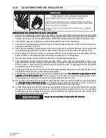
Tighten flexible gas hose and components securely.
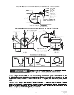
Flexible metal gas hoses must be installed without any twists or
kinks in them. The hose will move during operation of the heater
and it can crack if it is twisted.
Failure to do so may result in death, serious injury or property
damage.
IMPORTANT BEFORE CONNECTING THE GAS TO THE HEATER
IMPORTANT BEFORE CONNECTING THE GAS TO THE HEATER
IMPORTANT BEFORE CONNECTING THE GAS TO THE HEATER
IMPORTANT BEFORE CONNECTING THE GAS TO THE HEATER
1.
Connect to the supply tank or manifold in accordance with the latest edition of National Fuel Gas Code (ANSI
Z223.1), and local building codes. Authorities having jurisdiction should be consulted before the installation
is made. (In Canada, refer to the latest edition of CSA B149.1, Natural Gas and Propane Installation Code.)
2.
Check that the gas fuel on the burner rating plate matches the fuel for the application.
3.
Check that the gas supply piping has the capacity for the total gas consumption of the heaters and any other
equipment connected to the line.
4.
Check that the calculated supply pressure with all gas appliances and heaters operating will not drop below
the minimum supply pressure required for these heaters. Check inlet supply pressures on Section 14.0).
5.
All gas supply lines must be located in accordance with the required clearances to combustibles from the
heater as listed on the clearances label of the heater and Section 4.0) of this manual.
6.
Pipe joint compounds must be resistant to the action of liquefied petroleum gases.
7.
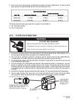
Tube heaters will expand/contract during operation. Where local codes do not prohibit, a CSA or U.L.
approved flexible connector supplied with this heater is required for connections between the rigid piping
and the heater. A union should be installed before the burner box inlet. An approved shut off valve should
be installed within 6 feet of the union.
8.
The gas pipe, flexible hose and connections must be self supporting. The gas pipe work must not bear any of
the weight of the heater or any other suspended assembly.
9.
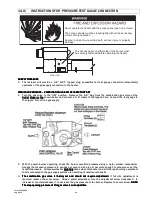
This appliance is equipped with a step-opening, combination gas valve. The maximum supply pressure to the
The maximum supply pressure to the
The maximum supply pressure to the
The maximum supply pressure to the
applia
applia
applia
appliance is 14” W.C. or 1/2 P.S.I.
nce is 14” W.C. or 1/2 P.S.I.
nce is 14” W.C. or 1/2 P.S.I.
nce is 14” W.C. or 1/2 P.S.I. If the line pressure is more than the maximum supply pressure, then a
second stage regulator which corresponds to the supply pressure must be used.
10.
After all gas connections have been made, make sure the heater and all gas outlets are turned off before
the main gas supply is turned on slowly
main gas supply is turned on slowly
main gas supply is turned on slowly
main gas supply is turned on slowly. Turn the gas supply pressure on and check for leaks. To check for
leaks, check by one of the methods listed in Appendix D of the National Fuel Gas Code.
11.
If a 2nd stage regulator is used, the ball valve down stream in the supply line must be closed when purging
the gas lines to prevent gas seeping through it. If initial gas pressure is higher than 14” w.c. the redundant
combination gas valve is designed to lock out. Pressure build-up in the supply lines prior to the heater must
be released before proper heater operation.
Do not use an open flame of any kind to test for leaks.
Do not use an open flame of any kind to test for leaks.
Do not use an open flame of any kind to test for leaks.
Do not use an open flame of any kind to test for leaks.


