Form 43343320
-16-
Aug 2012
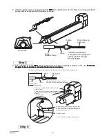
Typical Assembly Overview
(SPU 40FT Shown)
Wire Hanger
Flue
Terminal
#10 Self-Drill Screws
(Typical all tube supports,
tube couplings and flue
terminal.)
4"OD x 10Ft. Tube
See section 7
for required tubes.
13 Tube Support Brk.
with U-Bolt Clamp
& 5/16" Hex Nuts
Mounting Flange
24 Hole for Aluminized Steel Tubes
6 Hole for Alumi-Therm Steel Tubes
Gasket
Burner Box
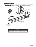
Typical
Overlap
U-Bend
Tube Coupling
(Typical each tube joint.)
Reflector
31 Tube Support Brk.
with U-Bolt Clamp
& 5/16" Hex Nuts
8 - 10
6 hanging points to be used for suspension for a typical
40ft long system. There must be two hanging points
on the first tube and one on each of the other tubes
Maximum 6 distance
from burner box to the
tube support/hanger
bracket.
8 - 9 ¼
#10 Self-Drill
Screws
(2 each)
Turbulator
(See specifications
section 5 for required
quantities.)
Burner Box
Suspension
Chain


