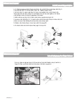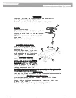
FIG-1
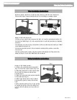
FIG-2
F
Installation:
Using a
e/ah
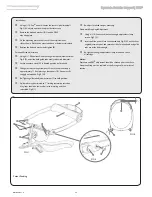
” Allen® wrench: Loosen the rear occipital screwball
Fig-1 (A), adjust up or down to provide slot access.
Remove the bolt and washer (B) from the DFS2
mounting plate.
Fit the mounting plate to the front of the occipital mount
slot as shown. Plate can be mounted above or below occipital pad.
Replace the bolt and washer and tighten (B)
.
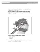
Forehead Strap Adjustment:
5
Using a
t/ds
” Allen wrench: Loosen the guide rods adjustment screw
Fig-2 (F), and slide both guide rods evenly to desired diameter.
6
Locate neoprene strap (D) in desired position on forehead.
7
Slide guide rods through clamp until front of neoprene strap is
approximately
q/s
” from plastic guide support (E). Strap must fit
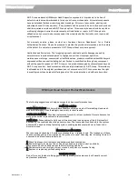
snuggly on forehead. Fig-3 (H)
8
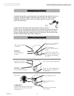
Re-Tighten guide rod adjustment screw (F) to hold position.
9
Guide rods may be trimmed to 1” limiting rearward protrusion.
Vinyl caps should be removed prior to trimming and then
reinstalled. Fig-3(I)
Re-adjust forehead strap as necessary.
Downward Stop Angle Adjustment:
Using a
t/ds
” Allen wrench loosen the angle adjustment clamp
screws Fig-1 (C).
Insert an Allen wrench into the exposed hole Fig-2 (G) on the silver
angle adjustment pivot and rotate until the forehead pad and guide
rods are at the desired angle.
Re-tighten the angle adjustment clamp screws and check
all settings.
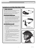
Notice:
Fasteners and DFS2 adjustment should be checked prior to each use.
Neoprene Strap must be replaced at the first signs of wear or loss of
tension.
q/s
”
FIG-3
G
1”
C
Patent Pending
C
E
D
H
I
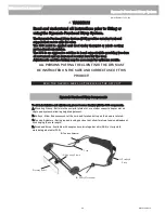
Whitmyer Head Supports
Dynamic Anterior Support| DFS
2
MKT6100 Rev. C
34

