background image

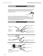
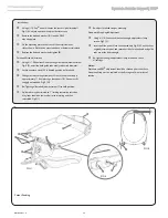
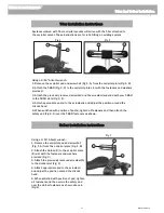
Using a 3/16” Allen® wrench:

1. Remove the occipital pad and screwball

(Fig. 1, A) from the occipital plate (Fig. 1, B).

2. Attach the Unibar (D) to the occipital plate

(B) slot with the fasteners and washers

provided (Fig. 3).

3. Attach the previously removed screwball(A)

to the Unibar slot (Fig. 3).

4. Attach appropriate pad to the screwball

and adjust the position around the client’s

head.

5. When satisfied with position of pad, tighten

all fasteners and then velcro the safety pad

over the Unibar fasteners as shown above in

(Fig.2).

Using a 3/16” Allen® wrench:

1. Remove the occipital pad and screwball (Fig.1, A) from the occipital plate (Fig.1, B).
2. Attach the T-BAR (Fig. 2, C) to the occipital plate slot with the fasteners and washers

provided.

3. Attach the previously removed screwball and the screwball supplied with your T-BAR

to the T-BAR slots (Fig.2, E).

4. Attach appropriate pad(s) to the screwballs and adjust the position around the

client’s head.

5. When satisfied with position of pad(s), tighten all fasteners and then attach the

safety pad (Fig.2, D) over the T-BAR fasteners as shown.

T-Bar Installation Instructions

Systems ordered with T-bar occipital mounts will arrive with the T-bar attached to 

the occipital mount. These instructions are for retro-fitting an existing system

Fig.3

Fig.2

Fig.1

Unibar Installation Instructions

A

B

C

D

E

A

B

D

Whitmyer Head Supports

T-Bar And Unibar Installation

37

MKT6100 Rev. C

Содержание Whitmyer DFSQ1

Страница 1: ...W H I T M Y E R H E A D S U P P O R T S S e r v i c e M a n u a l Whitmyer Head Supports WHITMYER ...

Страница 2: ...re used in the construction of this product are fully recyclable The separate collection and recycling of your product at the time of disposal will help conserve natural resources and ensure that it is disposed in a manner that protects the environment Ensure you are the legal owner of the product prior to arranging for the product disposal in accordance with the above recommendations SUNRISEMEDIC...

Страница 3: ...ort Attachment Contoured Cradle Lateral Support Option PLUSH Lateral Support Option S O F T Lateral Support Option Lateral Swingaway Lateral Facial Pad Positioning Contoured Cradle Anterior and Lateral Support Combination PLUSH Anterior and Lateral Support Combination Contoured Cradle PLUSH Pad Adjustment Adjust A PLUSH Pad Adjustment Single Sub occipital System Adjustment S O F T Multi Pad System...

Страница 4: ...ycra PRC7010 mounting PRO adult w mount M9375 base plate assm adult PED 3 piece 2 Attach mounting bracket to back of chair Reference pages 5 8 3 Assemble vertical horizontal assembly as described in Mounting Section of instructions Reference pages 9 14 Place vertical horizontal assembly into mounting bracket 4 Attach base plate assembly and or pads Reference pages 15 16 5 Assemble and attach later...

Страница 5: ...2 Recommended mount ing height to top of chair back is 2 Detachable Mounting Bracket ONYX M2100 LINX M2300 PRO M2200 Mounting hardware options T nuts or nylock nuts w washers Mounting hole spacing options 2 hole 1 7 8 or 2 Recommended mount ing height to top of chair back is PRO 2 LINX 5 ONYX 2 17 8 to 2 2 17 8 Whitmyer Head Supports Detachable Mounting Brackets 5 MKT6100 Rev C ...

Страница 6: ... 1 x 2 Recommended mounting height to top of chair back is PRO 2 LINX 5 ONYX 2 Note Vertical rod may need to be cut to enable complete swingaway arc Note Replace knob with 20 x bolt MW010210 to disable detach function Detachable Mount to Swingaway Upgrade A B C D E F ONYX M5100 LINX M5200 PRO M5300 Whitmyer Head Supports Swingaway Mount Upgrade MKT6100 Rev C 6 ...

Страница 7: ...Interface Plate M1010 Detachable Mount to Hole Spacing Conversion Plate M2010 45 8 1 2 33 16 2 A B C D E A B C Whitmyer Head Supports Custom Mounting Options 7 MKT6100 Rev C ...

Страница 8: ...hole 1 x 2 Note Old style hardware kit included for mounting older style Whitmyer Head Support detach and swingaway mounts Detachable Mount to Quick Mount M7000 Mounting hole spacing options 2 hole 1 and 2 24 12 NOTE Mounting clamps plate have full adjustability A B C D E F G H I Whitmyer Head Supports Custom Mounting Options MKT6100 Rev C 8 ...

Страница 9: ... to align the index pin in the slot on the detach mount Fig 1 F Vertical rod may be rotated for additional angle adjustment of pad base plate assembly 2 Horizontal Loosen collar screws Fig 1 B for depth adjustment Fig 2 Rotate horizontal rod 180º for increased angle pad base plate assembly adjustment 3 Tighten all collars bolts evenly to reach full locking strength See page 15 Fig 1 Fig 2 Fig 3 Fi...

Страница 10: ...pad base plate assembly 2 Depth and Angle Adjustment Loosen 3 adjustment screws Fig 1 B for depth and angle adjustment Fig 4 5 Rotate horizontal rod 180º for increased angle adjustment Fig 3 Reverse vertical rod 180º for increased adjustment Fig 3 3 Tighten all collar bolts evenly to reach full locking strength See page 15 Fig 1 B C D Fig 4 Fig 5 Fig 3 Fig 2 A A E Whitmyer Head Supports AXYS Mount...

Страница 11: ... Vertical Loosen the lever knob Fig 1 E and adjust to the proper height and then lower the stop collar Fig 1 C be sure to align the index pin in the slot on the detach mount Fig 1 F Vertical rod may be rotated for additional angle adjustment of pad base plate assembly 2 Horizontal Vertical Loosen clamp screws Fig 1 A B for depth and height adjustment Fig 2 3 Tighten all collar screws evenly to rea...

Страница 12: ...ay be rotated for additional angle adjustment of pad base plate assembly 2 Depth and Angle Adjustment Loosen adjustment screws Fig 1 A B for depth and angle adjustment Note angle adjustment shown in Fig 3 3 Tighten all collar bolts evenly to reach full locking strength See page 15 Fig 1 B A C Fig 3 Fig 2 C C D Whitmyer Head Supports COBRA XTRA Mounting System MKT6100 Rev C 12 ...

Страница 13: ...ent of pad base plate assembly 2 Depth and Angle Adjustment Loosen adjustment screws Fig 1 A B for depth and angle adjustment Note angle adjustment shown in Fig 3 3 To flip the headrest back push button Fig 4 D and swing unit back 4 Tighten all collar bolts evenly to reach full locking strength See page 15 Fig 1 B A C Fig 3 C D Fig 2 Fig 4 D Whitmyer Head Supports COBRA XTRA Flip Back Mounting Syst...

Страница 14: ... C be sure to align the index pin in the slot on the detach mount Fig 1 G Vertical rod may be rotated for additional angle adjustment of pad base plate assembly 2 Horizontal Angle Loosen pivot bolts Fig 1 A for depth Fig 4 and angle Fig 3 adjustments It is not necessary to fully tighten all screws until final position is achieved 3 Tighten all collar screws evenly to reach full locking strength Se...

Страница 15: ...iminate unwanted movement Fig 2A 2B Even though the knurled balls eliminate unwanted pad movement the collars must be evenly tightened to reach their full locking strength 1 Slide collar cover B off pad collar and over ball C 2 Loosen collar bolts A Loosen the collar bolts only to the point where the ball slides in This is easier than taking the collar halves completely apart 3 Clamp collar evenly...

Страница 16: ...5 4 Attach pads to screwballs D 5 Place vinyl cover E on to collar A Single Sub occipital Base Plate Assembly Attachment Fig 2 1 Remove bolts B and discard bottom collar half E of single sub occipital pad 2 Clamp the horizontal ball A between the single sub occipital pad top collar half B and the base plate collar adaptor C 3 Attach occipital pad to screwball D 4 Even though the knurled balls elim...

Страница 17: ...t Fig 2 A and washer Fig 2 B through the anterior support adapter bracket slot Fig 2 D clamping the anterior support option in place 5 Adjust to user See page 28 32 Fig 1 A B C E D Fig 2 C A B D Anterior Support Attachment to S O F T Base Plate Assemblies Fig 3 1 Remove bolt A and washer B from anterior support mount C 2 Align bolt A and washer B through the occipital mount slot D clamping the ant...

Страница 18: ...Fig 2 E 5 Refer to Fig 4 Loosen bolts Fig 4 A and clamp splitball Fig 4 B between the lateral mount collar halves Fig 4 C and tighten Do not securely tighten collar halves until fit ting to client to allow for adjustment of ballrod 6 Slide collar cover Fig 4 G off pad collar onto curved ballrod Fig 4 E 7 Loosen collar bolts Fig 4 D Loosening the collar bolts just to the point where the ball slides...

Страница 19: ...o Fig 4 Loosen bolts Fig 4 A and clamp splitball Fig 4 B between the lateral mount collar halves Fig 4 C and tighten Do not securely tighten collar halves until fit ting to client to allow for adjustment of ballrod 6 Slide collar cover Fig 4 D off pad collar onto curved ballrod Fig 4 E 7 Loosen collar bolts Fig 4 F Loosening the collar bolts just to the point where the ball slides in is easier tha...

Страница 20: ...Fig 1 A and washers Fig 1 B Tighten bolts securely 2 Refer to Fig 2 Loosen bolts Fig 2 A and clamp splitball Fig 2 B between the lateral mount collar halves Fig 2 C and tighten Do not securely tighten collar halves until fit ting to client to allow for adjustment of ballrod 3 Slide collar cover Fig 2 D off pad collar onto curved ballrod Fig 2 E 4 Loosen collar bolts Fig 2 F Loosening the collar bo...

Страница 21: ... that is occurring Carefully place the pad s in a position that will evenly distribute the pressure placed upon them to avoid discomfort Familiarize yourself with the various directions of adjustment A Linear adjustment B Height adjustment C Rotational adjustment WARNING Avoid positioning pad s directly on jawbone over ears or in an area that will come in contact with the user s eyes Should irrita...

Страница 22: ... plate assembly Fig 4 B using bolts Fig 4 C and washers Fig 4 D Completed assembly Fig 4 E Tighten securely Swingaway lateral mount may be applied left or right or used in unilateral or bilateral configurations 5 Refer to Fig 5 Evenly clamp horizontal ball Fig 5 A between top collar half Fig 5 B and completed anterior lateral assembly Fig 5 C 6 See page 19 steps 5 9 for LFC ballrod assembly 7 See ...

Страница 23: ...or lateral interface plate assembly Fig 4 B using bolts Fig 4 C and washers Fig 4 D Tighten securely Swingaway lateral mount may be applied left or right or used in unilateral or bilateral configurations 5 Refer to Fig 5 Evenly clamp horizontal ball Fig 5 A between top collar half Fig 5 B and completed anterior lateral assembly Fig 5 C 6 See page 19 steps 5 9 for LFC ballrod assembly 7 See page 17...

Страница 24: ...ig 2 Contoured Cradle pads are designed to provide lateral cer vical and sub occipital support in a single pad The pad should be adjusted to provide even contact across its surface and allow the flared tips to support the cervical spine just under the ears and behind the mastoid process Gently bend flared sections in to place by hand to accom modate various neck widths Whitmyer Head Supports Conto...

Страница 25: ...ned to provide comfortable support to the upper cervical and sub occipital areas The pad should cradle the spine and provide lift under the occiput Fig 1 Centering the pad at the apex of the occiput forces the cervical spine into flexion Fig 2 Fig 1 Fig 2 NOTE The pad should cradle the spine and provide lift under the occiput Fig1 WARNING Centering the pad at the apex of the occiput forces the cerv...

Страница 26: ...ows anterior posterior movement of the occipital mount and pad The sub occipital pad should be adjusted to provide lateral cervical support and lift under the occiput The flared tips of the pad should extend under the ears and below the mastoid process Fig 1 3 Fig 2 Adjust the occipital pad forward just enough to come into contact with the occiput Fig 4 Loosening bolts B allows the pad to be moved...

Страница 27: ...cipital pad rotation D occipital pad depth E occipital pad height F occipital pad rotation 3 Adjust the height and depth of the mounting system to place the head support in the general position of the sub occipital and occipital regions of the head Fig 3 4 Gently slide the head support forward allowing the sub occip ital pads to make soft initial contact Secure the position of the mounting system ...

Страница 28: ... pad too low May be against shoulder caus ing discomfort Top edge of occipital pad taking too much pressure Better distribution of forces Ear and mastoid process clearance Flared tab of sub occipital above shoulder X ray of system CORRECT System tilted at angle which allows upper and lower pads to provide a more evenly distribute pressure AdjustingTheSystemToTheUser WhatToLookForInACorrectFit Whit...

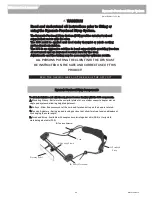
Страница 29: ...AND CORRECT USE OF THIS PRODUCT Patent Number 5 306 232 READ THE WARNING LABEL ON THE BACK OF THE DFS UNIT Cord B Pulley Mechanism D Forehead Strap A Mounting Clamp Warning Label To aid in installation and adjustment please become familiar with the DFS components A Mounting Clamp Bolts into the occipital plate slot or anterior support adapter slot on single pad systems allowing height adjustment B...

Страница 30: ...tem in its correct application Refer to a qualified therapist or rehab technology supplier trained in postural positioning should DFS adjustments be necessary MistakesCommonly Made While AdjustingThe DynamicForeheadStrap Pulleys too low Strap slips down over the eyes Pulleys too high Strap rides up over head WRONG Pulleys mounted too low causing strap to ride down on ears eyes SOLUTION Raise pulle...

Страница 31: ...e client in the chair ensure the head support system is cor rectly installed refer to the previous sections on system installation Slide the forehead strap into position Fig 1 STEP 2 Tensioning the strap Using the tension adjusters tighten the strap to the point required to maintain constant forehead contact but not tight enough to cause redness from excessive pressure Fig 2 Warning The user s hea...

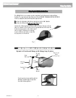
Страница 32: ...re installation instruction for the DFS System 2 Follow the fitting instructions for the DFS System Sizing the Strap Cap Include the following step to custom size the cap to the user s head Insert or remove one or both pieces of pre shaped foam A from the hook and loop pouch on the inside top of the cap Fig 1 Inserting or removing a piece of foam will raise or lower the cap s position on the head ...

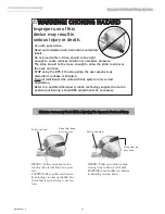
Страница 33: ...F INJURY AND HOW TO AVOID THEM Excess Movement or Migration of the Pelvis This may cause the support to displace If this occurs severe injury to the client could result To avoid the risk A It is VITAL to keep the client in a stable pelvic position Anterior supports should ONLY be used with seat back and pelvic supports or belts that keep the client from sliding down in the seat B Anterior supports...

Страница 34: ...rt E Strap must fit snuggly on forehead Fig 3 H 8 Re Tighten guide rod adjustment screw F to hold position 9 Guide rods may be trimmed to 1 limiting rearward protrusion Vinyl caps should be removed prior to trimming and then reinstalled Fig 3 I Re adjust forehead strap as necessary Downward Stop Angle Adjustment Using a t ds Allen wrench loosen the angle adjustment clamp screws Fig 1 C Insert an A...

Страница 35: ...gs before using the product Installation Using a 3 16 Allen wrench 1 Loosen the rear occipital screwball A adjust up or down to provide slot access 2 Remove the bolt and washer B from the HEDZ UP mount ing bracket 3 Fit the mounting plate to the front of the occipital plate slot as shown 4 Replace the bolt and washer B Note Adjust the strap to allow a space of one or two fingers between the user s...

Страница 36: ...r half of occipital pad F 3 Adjust support as desired and tighten all screws securely D E C B A F D F A B C E Application Consideration CAUTION Use only when child can be monitored Anterior strap should not be used with children who may grab or pull the support strap Only for use for children under 3 years of age Not to be attached or modified for use with products other than Cuddles Not appropria...

Страница 37: ... occipital plate Fig 1 B 2 Attach the T BAR Fig 2 C to the occipital plate slot with the fasteners and washers provided 3 Attach the previously removed screwball and the screwball supplied with your T BAR to the T BAR slots Fig 2 E 4 Attach appropriate pad s to the screwballs and adjust the position around the client s head 5 When satisfied with position of pad s tighten all fasteners and then att...

Страница 38: ...ge caused by normal wear or to products subjected to negligence accident improper operation maintenance or storage commercial or institutional use products modified without Whitmyer s expressed written consent including but not limited to modification through any component without the specific consent of A R T Group or to a product damaged by circumstances beyond A R T Group s control Such evaluat...

Страница 39: ...Whitmyer Head Supports Notes 39 MKT6100 Rev C ...

Страница 40: ... 2016 SunriseMedical US LLC 12 16 MKT6100 Rev C ...

Отзывы: