


74 SUNFAR C300
C300 series of non-sensor current vector-control inverter manual
3
:
External voltage signal VC
(
0V~10V
)
。
4
:
External current signal CC
(
0~20mA
)
。
The second part of LED
:
Reserved.
The third part of LED
:
It is used for setting PID feedback channel.
0
:
External voltage input VC is as feedback channel, which is in the range of
0~10V.
1
:
External current input CC is as feedback channel, which is in the range of
0~20mA.
2
:
VC+CC Feedback value is composed of VC1 and CC.
3
:
VC-CC Feedback value is that VC1 minus CC.
4
:
Min (VC, CC) Feedback value is min value between VC and CC.
5
:
Max (VC, CC) Feedback value is max value between VC and CC.
The fourth part of LED: Reserved.
If F8.1 is 0#00, setting value will be set by F8.2.
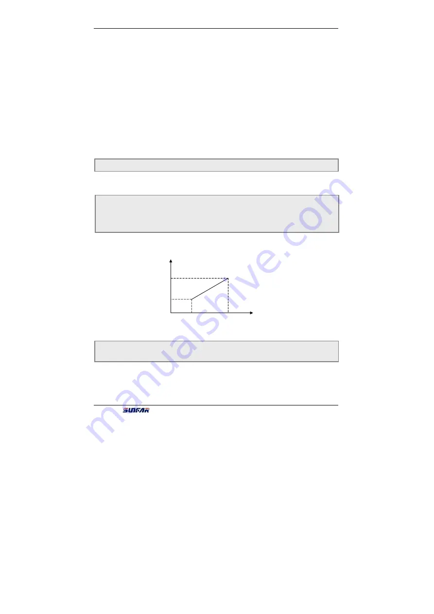
Parameters F8.3 and F8.4 define the upper and lower limit value of PID setting.
Parameters F8.5 and F8.6 define corresponding relation with PID feedback value.
Shown as fig.6-31.
Those parameters are inner parameter of PID.
F8.2 Inner PID close-loop digital setting Setting range
:
0.0 ~ 10.00V
F8.3 Minimum fixed value
Setting range
:
0.0 ~ [F8.4]
F8.4 Maximum fixed value
Setting range
:
[F8.3] ~ 10.00
F8.5 Feedback of minimum fixed value Setting range
:
0.0 ~ 10.00
F8.6 Feedback of maximum fixed value Setting range
:
0.0 ~ 10.00
F8.7 Proportion gain Setting range
:
0.0 ~ 5.00
F8.8 Integral time constant Setting range
:
1.0 ~ 100 Sec
Expected feedback value
[F8.6]
[F8.5]
[F8.3]
[F8.4]
PID setting value
Fig.6-31 Relation between PID fixed value and expected feedback value


