background image

Appendix B

Using the Tools and Drivers CD

B-3

B.2.2

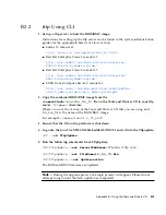
tftp Using CLI

1. Set up a tftp server to host the BIOS/BMC image.

Instructions for setting up the tftp server can be found in the system administration
guides for the appropriate Solaris or Linux version:

Solaris 10 manual at:

http://docs.sun.com/app/docs/doc/817-5504

Red Hat Enterprise Linux 3 manual at:

http://www.redhat.com/docs/manuals/enterprise/

RHEL-3-Manual/sysadmin-guide/

Red Hat Enterprise Linux 4 manual at:

http://www.redhat.com/docs/manuals/enterprise/

RHEL-4-Manual/sysadmin-guide/

SUSE Linux Enterprise Server 9 manual at:

http://www.novell.com/documentation/sles9/pdfdoc/

sles_9_admin_guide/sles_9_admin_guide.pdf

2. Copy the combined BIOS/BMC image from the

/remoteflash/

version

/

bios_bmc_file

file on the Tools and Drivers CD to your tftp

server

/tftpboot

directory.

Where

version

is the version of the Tools and Drivers CD that you are using and

bios_bmc_file

is the name of the BIOS/BMC image.

For example:

/remoteflash/1.0/90_3A02

3. Ensure that the OS on the platform is shut down.

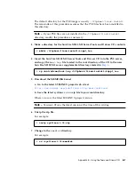
4. Log onto the Sun Fire X2100 M2 Embedded LOM CLI and cd into the Tftpupdate:

/SP ->

cd TftpUpdate

5. Run the following commands from TftpUpdate:

/SP/TftpUpdate ->

set ServerIPAddress

=

IP address of tftp server

/SP/TftpUpdate ->

set FileName=

bios_bmc_file

.bin

/SP/TftpUpdate ->

set Update=action

The BIOS and BMC firmware are updated.

Note –

During the upgrade process, the login prompt will appear. Please do not

attempt to login until the flash update has completed.

Содержание Sun Fire X2100 M2

Страница 1: ...Sun Microsystems Inc www sun com Submit comments about this document at http www sun com hwdocs feedback Sun Fire X2100 M2 Server Service Manual Part No 819 6591 11 December 2006 Revision A ...

Страница 2: ...yright 2006 Sun Microsystems Inc 4150 Network Circle Santa Clara Californie 95054 Etats Unis Tous droits réservés Sun Microsystems Inc a les droits de propriété intellectuels relatants à la technologie qui est décrit dans ce document En particulier et sans la limitation ces droits de propriété intellectuels peuvent inclure un ou plus des brevets américains énumérés à http www sun com patents et un...

Страница 3: ...are 1 4 1 2 4 System Management 1 4 1 3 Hardware System Overview 1 5 1 3 1 Front and Back Panels 1 5 1 3 2 Internal Components 1 7 1 4 Powering On and Powering Off the Server 1 8 1 4 1 To Apply Standby Power for Initial Service Processor Configuration 1 8 1 4 2 Powering On Main Power Mode 1 9 1 4 3 Shutting Down Main Power Mode 1 9 1 4 4 Clearing the CMOS 1 10 1 5 Customer Orderable Components 1 1...

Страница 4: ...Disk 3 6 3 4 Immediate Burn in Testing 3 7 3 5 Deferred Burn in Testing 3 9 3 6 Create Diagnostic Partition Option 3 10 3 6 1 Removing Existing Partitions From a Hard Disk 3 11 3 6 2 Adding a Diagnostic Partition to the First Bootable Disk 3 12 3 6 3 Creating a Log File on the Diagnostic Partition 3 12 3 6 4 Accessing the Diagnostic Partition on a Red Hat Linux System 3 13 3 6 5 Accessing the Diag...

Страница 5: ...ser Assembly and PCIe Card 4 9 4 5 2 2 Installing the PCIe Card and Riser Card Assembly 4 10 4 5 3 Replacing a Hard Disk Drive and Carrier 4 12 4 5 3 1 Removing an HDD and Carrier 4 12 4 5 3 2 Installing an HDD and Carrier 4 13 4 5 4 Installing a LSI PCIe Card and Cables 4 14 4 5 4 1 Installing the LSI Card to Support SAS Hard Drive Installation 4 14 4 5 4 2 Installing the LSI Card to Support SATA...

Страница 6: ...M Population Rules 4 31 4 5 10 2 Removing a DIMM 4 31 4 5 10 3 Installing a DIMM 4 33 4 5 11 Replacing the System Battery 4 35 4 5 11 1 Removing the System Battery 4 35 4 5 11 2 Installing the System Battery 4 37 4 5 12 Replacing a CPU and Heatsink 4 38 4 5 12 1 Removing a CPU and Heatsink 4 38 4 5 12 2 Installing a CPU and Heatsink 4 40 4 5 13 Replacing Cables 4 43 4 5 14 Replacing the Motherboar...

Страница 7: ...software How This Book Is Organized Chapter 1 provides an overview of the Sun Fire X2100 M2 Server Chapter 2 contains information about troubleshooting the server Chapter 3 provides information about diagnostics Chapter 4 describes how to remove and replace components Appendix A contains information on system specifications Appendix B provides information on using the Sun Fire X2100 M2 Server Tool...

Страница 8: ...up to date than the translated documentation For all Sun hardware documentation see the following URL http www sun com documentation For Solaris and other software documentation see the following URL http docs sun com Typeface1 1 The settings on your browser might differ from these settings Meaning Examples AaBbCc123 The names of commands files and directories onscreen computer output Edit your lo...

Страница 9: ...any actual or alleged damage or loss caused by or in connection with the use of or reliance on any such content goods or services that are available on or through such sites or resources Warranty For specific details regarding your warranty visit http www sun com service support warranty index html Sun Function URL Description Documentation http www sun com documentation Download PDF and HTML docu...

Страница 10: ...in improving its documentation and welcomes your comments and suggestions You can submit your comments by going to http www sun com hwdocs feedback Please include the title and part number of your document with your feedback The part number of this Sun Fire X2100 M2 Server Service Manual is 819 6591 11 ...

Страница 11: ...ures and information about installing components The following sections are included in this chapter Section 1 1 Features on page 1 2 Section 1 2 Operating System and Software on page 1 3 Section 1 3 Hardware System Overview on page 1 5 Section 1 4 Powering On and Powering Off the Server on page 1 8 Section 1 5 Customer Orderable Components on page 1 10 ...

Страница 12: ...d Media storage Optional DVD ROM or DVD RW Hard disk drives Up to two SATA or SAS 3 5 inch optional disk drives with NVIDIA and LSI RAID supported LSI PCIe card needed Power supply 345W PSU Network I O Four 10 100 1000BASE T Gigabit Ethernet ports PCI I O Optional PCI Express PCIe riser card with two 8 lane slots supporting low profile half length PCIe cards up to 25W Other I O Four USB 2 0 connec...

Страница 13: ...1 2 2 Supported Operating Systems The following operating systems or later versions are supported for the Sun Fire X2100 M2 server Solaris 10 Operating System 6 06 or later version with Sun Java Enterprise System Java ES Red Hat Enterprise Linux 3 Update 7 or later 32 and 64 bit ES and AS Red Hat Enterprise Linux 4 Update 3 or later 32 and 64 bit ES and AS SUSE Linux Enterprise System 9 SP 3 or la...

Страница 14: ...o be installed 1 2 3 Tools and Drivers CD Software The Sun Fire X2100 M2 Server Tools and Drivers CD included with the server contains drivers for operating system installation LSI and NVIDIA RAID drivers BIOS BMC flash utilities diagnostics software Windows Remote Installation Service RIS files and Broadcom NetXtreme software For more information on using the Tools and Drivers CD software see App...

Страница 15: ...ver 1 3 1 Front and Back Panels FIGURE 1 1 shows the front panel of the Sun Fire X2100 M2 server FIGURE 1 1 Front Panel TABLE 1 2 Front Panel Label Button LED Port Label Button LED port 1 System identification button LED 5 Optional hard disk drive 0 2 Fault LED 6 USB 2 0 connectors 2 3 Power LED 7 Optional DVD drive 4 Power button 8 Optional hard disk drive 1 2 1 3 4 5 6 7 8 ...

Страница 16: ... Label Connector Slot Label Connector Slot 1 Power connector 6 NVIDIA Ethernet connectors LAN 2 left LAN 3 right 2 Broadcom Ethernet connectors LAN 0 top LAN 1 NET MGT bottom 7 Serial management DB9 RS 232 serial port 3 System identification LED 8 PCI Express slots 4 Fault LED 9 Onboard HD15 video connector 5 Power LED 10 USB 2 0 connectors 4 1 2 10 9 6 3 4 5 7 8 ...

Страница 17: ... Fire X2100 M2 Server System Components TABLE 1 4 Sun Fire X2100 M2 Server Internal Components Label Component Label Component 1 PCI Express riser and cards 7 I O board 2 Power supply 8 Single fan module 3 Optional hard drive 1 9 Air duct 4 Dual blower module 10 CPU heatsink 5 Optional DVD drive 11 DIMM slots 4 6 Optional hard drive 0 12 Battery 1 2 3 6 7 8 4 9 5 10 11 12 ...

Страница 18: ...onfiguration Caution Do not operate the server without all fans component heatsinks air baffles and the cover installed Severe damage to server components can occur if operated without adequate cooling mechanisms 1 Connect grounded AC power cord to the AC power connector on the back panel of the server and to grounded AC power outlets Note At this point standby power is supplied only to the servic...

Страница 19: ...ain power mode use one of the following two methods Graceful shutdown Use a ballpoint pen or stylus to press and release the Power button on the front panel This causes Advanced Configuration and Power Interface ACPI enabled operating systems to perform an orderly shutdown of the operating system Servers not running ACPI enabled operating systems will shut down to standby power mode immediately Em...

Страница 20: ...e AC power cord See FIGURE 1 2 for the location of the power cord connection 2 Remove the battery for 30 seconds then reinsert it See Chapter 4 for instructions on removing and replacing the battery 3 Reinsert the AC power cord 1 5 Customer Orderable Components You can order additional components and replacement parts for the Leo server Contact your local Sun sales representative for more informat...

Страница 21: ...on troubleshooting procedures and technical support contacts The following sections are included in this chapter Section 2 1 Troubleshooting Overview on page 2 2 Section 2 2 Performing Visual Inspections on page 2 2 Section 2 3 Troubleshooting Procedures on page 2 4 ...

Страница 22: ...ection 2 2 Performing Visual Inspections on page 2 2 View the troubleshooting procedures in Section 2 3 Troubleshooting Procedures on page 2 4 to see if any of them solve the problem Execute a diagnostics test as described in Chapter 3 2 2 Performing Visual Inspections Improperly set controls and loose or improperly connected cables are common causes of problems with hardware components When inves...

Страница 23: ...ting system if necessary 2 Disconnect the power cord from the back of the system 3 Turn off any attached peripherals 4 Remove the server cover following the procedures in Section 4 2 Installation Precautions on page 4 2 Caution Some components such as the heatsink can become extremely hot during system operations Allow these components to cool before handling them 5 Verify that the components are ...

Страница 24: ...Server powers on but the monitor does not Is the Power button for the monitor turned on Is the monitor power cord connected to a wall outlet Does the wall outlet have power Test by connecting another device CD or DVD does not eject from the media tray when you press the Eject button Move the mouse or press any key on the keyboard The drive might be in the low power mode Use the utility software in...

Страница 25: ...lluminated Server appears to be in low power mode but the Power button LED does not blink The power indicator LED only blinks when all server components are in low power mode A tape drive might be connected to your server Because tape drives do not enter low power mode the power indicator LED does not blink Hung or frozen server No response from mouse or keyboard or any application Try to access y...

Страница 26: ...xclusively over the serial line External device is not working Check the documentation that came with the device to see if any device drivers must be installed Ensure that the cables for the external device are firmly connected and that the pins in the cable and connector are not bent Power off the system reattach the external device and power on the system Newly installed memory is not detected M...

Страница 27: ...diagnose and resolve these issues The following sections are included in this chapter Section 3 1 Pc Check Diagnostics Overview on page 3 2 Section 3 2 System Information Menu Options on page 3 3 Section 3 3 Advanced Diagnostics Tests Menu Options on page 3 4 Section 3 4 Immediate Burn in Testing on page 3 7 Section 3 5 Deferred Burn in Testing on page 3 9 Section 3 6 Create Diagnostic Partition O...

Страница 28: ... Pc Check Diagnostics Software 1 Do one of the following depending on which method you are using to access the Pc Check diagnostics software If your server has a DVD drive installed Insert the Sun Fire X2100 M2 Server Tools and Drivers CD into your DVD drive and reboot the system If you are running the Pc Check software from a PXE server Follow the instructions in Appendix C to set up the PXE serv...

Страница 29: ...r system including comparisons between the updates and the newest versions of your system XML is the format used to create and display this information though you can also choose a text format txt as well System Management Information Provides information obtained from the system about the BIOS type system motherboard enclosure processors memory modules cache slots system event log memory array me...

Страница 30: ...tor CPU Frequency Monitor Tests the processor speed CMOS RAM Utilities Shows the CMOS settings of the system SCSI Utilities Not applicable for the Sun Fire X2100 M2 server Text File Editor Opens a file editor Start Up Options Enables you to set up options for diagnostics testing TABLE 3 2 Advanced Diagnostics Tests Menu Options Option Description Processor Details information about the processor a...

Страница 31: ...r ATA Includes an ATA test menu USB Details information about the USB devices on the system and includes a USB Tests menu to test the USB FireWire Not applicable for the Sun Fire X2100 M2 server Network Performs network register controller tests Keyboard Includes a Keyboard Test menu with options for performing different tests on the keyboard Mouse Details information about the mouse and includes ...

Страница 32: ...rite Test and the Destructive Write Test These tests are relevant to testing the media associated with the hard drive hardware such as the physical disk Caution Running the Destructive Write Test destroys any data that is on the disk The Device Test options include the Mechanics Stress Test and the Internal Cache Test These tests are relevant to testing non media related devices associated with th...

Страница 33: ... tests cannot be run unattended and do not contain any timeout facilities The interactive tests will wait until the user provides the correct input noinput tst This script is used as a first triage of any hardware related problems or issues The script performs a high level test of most hardware components excluding those components that require user input keyboard mouse sound video This test does ...

Страница 34: ...t Script All Possible Choices Pass Control Overall Time Overall Passes Individual Passes Overall Passes or Overall Time Duration 01 00 1 Any number to designates the time duration of the test Script File N A quick tst noinput tst or full tst quick tst noiniput tst or full tst Report File None None User defined Journal File None D noinput jrl D quick jrl or D full jrl User defined Journal Options F...

Страница 35: ...e created Change Options Opens the Burn in Options menu which enables you to modify the various options listed in TABLE 3 3 for the currently loaded test script Select Tests Opens a listing of the tests available for your server configuration and the currently loaded test script Perform Burn in Tests Runs the currently loaded burn in test script 3 5 Deferred Burn in Testing You can use the Deferre...

Страница 36: ...The Create Diagnostic Partition option installs a diagnostic partition on the first bootable disk seen by the Sun Fire X2100 M2 server The first bootable disk is on the primary master SATA device Note If you are running the Pc Check Diagnostics software from a PXE server you do not need to follow the instructions in these procedures for inserting the Tools and Drivers CD into the DVD tray The foll...

Страница 37: ... tray 2 Reboot the server 3 From the Tools and Drivers CD main menu type 4 to exit to DOS 4 Type fdisk at the command prompt and press the Enter key 5 Type 4 to select an alternate fixed disk The second hard disk as seen from fdisk is the first bootable disk of the system The first hard disk as seen from fdisk is the bootable Tools and Drivers CD Caution When performing the following tests be care...

Страница 38: ... Partitioning complete Your machine will now be restarted If the first bootable disk is not clear of partitions a window appears stating that the software is unable to create a hardware diagnostic partition because there are already partitions on the disk If this happens go to Section 3 6 1 Removing Existing Partitions From a Hard Disk on page 3 11 to remove the partitions from the disk Repeat Ste...

Страница 39: ... have created 7 Select Perform Burn in Tests to run the script 8 When the tests are complete press the Esc key to exit the Display Results window 9 Select Exit to DOS and press Enter 10 At the DOS prompt type the following 11 Type the following to list the contents of the diagnostic partition The noinput jrl log is displayed 3 6 4 Accessing the Diagnostic Partition on a Red Hat Linux System To acc...

Страница 40: ...the diagnostic partition All users have read access to this partition Only the superuser has read write access to this partition You do not need to continue this procedure 5 Insert the Tools and Drivers CD into the DVD tray 6 When the CD is mounted open a terminal window 7 Type the following command Where mountpoint is the CD mountpoint and linux_version is the version of Linux that you have insta...

Страница 41: ...ed to be mounted If this command fails to list the log files created by the hardware diagnostics software then the operating system has never been configured to mount the diagnostic partition Continue to Step 5 If this command succeeds in listing the log files created by the hardware diagnostics software then the operating system has already been configured to mount the diagnostic partition All us...

Страница 42: ...ic partition There is no way to view or gain access to the diagnostic partition if you are running Windows 2003 on a Sun Fire X2100 M2 server The only way to retrieve the contents log files on the diagnostic partition is to attach a USB diskette drive to the Sun Fire X2100 M2 server and complete the following procedure 1 Connect the USB diskette drive to any USB port on the Sun Fire X2100 M2 serve...

Страница 43: ...ruction Set SSE2 Instruction Set and MP Symmetry Motherboard This section shows the following tests conducted against the motherboard DMA Controller Tests System Timer Tests Interrupt Test Keyboard Controller Tests PCI Bus Tests and CMOS RAM Clock Tests Memory Cache Memory and Video Memory This section shows the following tests conducted against the various types of memory Inversion Test Tree Prog...

Страница 44: ...st the hard disk Read Test Read Verify Test Non Destructive Write Test Destructive Write Test Mechanics Stress Test and Internal Cache Test USB This section shows the following tests conducted against the USB Controller Tests and Functional Tests Hardware ID The compare test is used to determine the machine ID for the system This test is not available for the Sun Fire X2100 M2 server 3 8 Print Res...

Страница 45: ...Chapter 3 Performing Diagnostics 3 19 3 10 Exit to DOS You use the Exit to DOS option to exit Pc Check and return to the DOS prompt ...

Страница 46: ...3 20 Sun Fire X2100 M2 Server Service Manual December 2006 ...

Страница 47: ...faulty component refer to Performing Diagnostics on page 3 1 Note System cooling might be affected by dust and contaminant build up It is recommended that systems be opened and checked approximately every six months or more often in dirty operating environments Check system heatsinks fans and air openings If necessary clean systems by brushing or blowing contaminants from the system or by carefull...

Страница 48: ...a wrist strap and attach it to the system chassis ground or to any metal part of the system before handling components Turn off the power button on the front of the chassis before removing or replacing any of the system components 4 2 2 Preinstallation Instructions Always perform the following steps before you install any component 1 Turn off the system and all of the peripherals connected to it C...

Страница 49: ...nd Powering Off the Server on page 1 8 Caution If the cover and hard disk drives bays do not have a hard drive or filler panel installed do not operate the server for more than ten minutes Improper cooling airflow might damage the system s components 4 3 Powering Off the Server and Removing the Cover For your safety perform this procedure when you are powering off the system and removing the cover...

Страница 50: ...sitive to static electricity 5 Before handling components attach a wrist strap to a chassis ground any unpainted metal surface 6 Loosen the two captive screws securing the cover to the chassis see FIGURE 4 1 7 Pull the cover slightly toward the back of the server and then straight up to remove it 8 Lift the cover and remove it FIGURE 4 1 Removing the Server Cover ...

Страница 51: ... Server System Components TABLE 4 1 Sun Fire X2100 M2 Server Internal Components Label Component Label Component 1 PCI Express riser and cards 7 I O board 2 Power supply 8 Single fan module 3 Optional hard drive 1 9 Air duct 4 Dual blower module 10 CPU heatsink 5 Optional DVD drive 11 DIMM slots 4 6 Optional hard drive 0 12 Battery 1 2 3 6 7 8 4 9 5 10 11 12 ...

Страница 52: ...nstalling an ODD Drive Assembly on page 4 19 Air duct see Section 4 5 6 Replacing an Air Duct on page 4 22 Power supply see Section 4 5 7 Replacing the Power Supply on page 4 24 Single fan modules see Section 4 5 8 Replacing the Single Fan on page 4 26 Dual blower module see Section 4 5 9 Replacing the Dual Blower Module on page 4 28 Memory DIMMs see Section 4 5 10 Replacing Memory Modules on page...

Страница 53: ...he server including any attached peripherals and disconnect the server from the electrical outlet Refer to Section 4 3 Powering Off the Server and Removing the Cover on page 4 3 2 Remove all cables connected to the I O board 3 Remove the screws securing the I O board to the DVD cage FIGURE 4 3 Removing the I O Board 4 Pull the I O board back slightly then upwards to disengage the board from the gu...

Страница 54: ...gs on the board line up with the guides on top of the HDD cage FIGURE 4 4 Installing the I O Board 2 Gently push the I O board down to engage the guides and push the board forward to secure it 3 Fasten the screws to secure the I O board to the mounting bracket 4 Reconnect the cables 5 Before reinstalling the cover on the server check the routing of all cables for obstructions ...

Страница 55: ... or install a PCIe card 4 5 2 1 Removing the Riser Assembly and PCIe Card To remove the PCIe riser assembly and PCIe card 1 Power off the system and remove the cover as described in Section 4 3 Powering Off the Server and Removing the Cover on page 4 3 FIGURE 4 5 Removing the PCIe Card Riser Assembly 2 Placing your fingers on the two green areas on the riser card pull the assembly upward and out o...

Страница 56: ...mber 2006 FIGURE 4 6 Removing a PCIe Card 4 5 2 2 Installing the PCIe Card and Riser Card Assembly To install the PCIe card and riser card assembly 1 If necessary remove the riser card filler panel FIGURE 4 7 Removing the PCIe Riser Card Filler Panels ...

Страница 57: ...ver 4 11 2 Connect the new PCIe in the riser assembly and fasten the latch to secure it FIGURE 4 8 Installing a PCIe Card 3 Reinstall the riser assembly and card in the connector on the motherboard FIGURE 4 9 Installing the PCIe Card Riser Assembly ...

Страница 58: ...g an HDD and Carrier To remove the HDD and carrier 1 If you are not using an integrated mirroring configuration you must power off the server before removing an HDD it is not necessary to remove the cover Power off the system as described in Section 4 3 Powering Off the Server and Removing the Cover on page 4 3 If you are using an IM configuration start with Step 2 2 Squeeze the release latch and ...

Страница 59: ... 3 2 Installing an HDD and Carrier on page 4 13 4 5 3 2 Installing an HDD and Carrier Note If you are installing a new HDD rather than replacing an already installed HDD you will need to remove the empty carrier from the drive cage before installing the new HDD See instructions for Removing an HDD and carrier To install the HDD and carrier 1 Squeeze the release latch and carefully swing the arm to...

Страница 60: ...ing Installing the LSI Card to Support SAS Hard Drive Installation on page 4 14 Installing the LSI Card to Support SATA RAID on page 4 17 4 5 4 1 Installing the LSI Card to Support SAS Hard Drive Installation If your system originally had SATA drives installed or came diskless and you would like to install SAS drives use the following procedure You will need to order the following components neede...

Страница 61: ...motherboard connector then connect the red cable to the HDD 0 backplane Disconnect the blue cable from the hard drive backplane and the motherboard connector then connect the blue cable to the HDD 1 backplane Make sure to route the blue cable through the dual blower routing clips FIGURE 4 12 SAS Drive Cable Routing 4 Remove the riser assembly from the server See Section 4 5 2 1 Removing the Riser ...

Страница 62: ...into the server yet It will be easier to connect the cables with the card outside of the system 6 Connect the SAS cables to the SAS card connectors See FIGURE 4 13 Connect the red cable to PHY 0 Connect the blue cable to PHY 1 FIGURE 4 13 Installing an LSI PCIeCard 7 Install the riser assembly into the server See Section 4 5 2 2 Installing the PCIe Card and Riser Card Assembly on page 4 10 8 Repla...

Страница 63: ...HDDs if not already installed The following procedure describes how to add the LSI PCIe card and cables to connect to the SATA hard disks 1 Power off the system and remove the cover as described in Section 4 3 Powering Off the Server and Removing the Cover on page 4 3 2 Reroute the hard drive cables See FIGURE 4 14 Note the following guidelines for cable removal and installation Disconnect the red...

Страница 64: ... page 4 9 4 Install the LSI PCIe card into the riser assembly See Section 4 5 2 2 Installing the PCIe Card and Riser Card Assembly on page 4 10 Do not install the riser card into the server yet It will be easier to connect the cables with the card outside of the system 5 Connect the SATA cables to the LSI PCIe card connectors See FIGURE 4 13 Connect the red cable to PHY 0 Connect the blue cable to...

Страница 65: ...sembly on page 4 10 7 Replace the system cover 8 Install the SATA hard drives if necessary See Section 4 5 3 2 Installing an HDD and Carrier on page 4 13 4 5 5 Removing and Installing an ODD Drive Assembly The following procedure describes how to replace the optical disk drive ODD assembly If you are not replacing a DVD drive go straight to Section 4 5 5 2 Installing the ODD Drive Assembly on page...

Страница 66: ...ing the Cover on page 4 3 2 Unfasten the drive ribbon cable from the ODD drive Caution Use care with the small flat cables They are extremely fragile FIGURE 4 16 Removing the DVD Drive Assembly 3 Push the latch on the back of the ODD drive toward the drive until the ODD drive springs forward out of the chassis 4 Pull the ODD drive out the front of the chassis Caution Move the assembly by grasping ...

Страница 67: ...ler panel in front of the ODD drive slot on the front panel Put your finger or a screw driver behind the slot on the right side of the filler panel and pull the panel outward FIGURE 4 17 Removing the DVD Drive Filler Panel 2 Position the ODD drive in front of the ODD drive slot on the front panel 3 Push the ODD drive into the drive slot until the drive clicks into place ...

Страница 68: ...uctions and then reinstall the cover 4 5 6 Replacing an Air Duct The following procedures describe how to replace the system air duct 4 5 6 1 Removing the Air Duct To remove the air duct 1 Power off the system and remove the cover as described in Section 4 3 Powering Off the Server and Removing the Cover on page 4 3 2 Remove the screw fastening the air duct to the chassis divider ...

Страница 69: ...4 19 Air Duct Removal 4 5 6 2 Installing the Air Duct To install the air duct 1 Position the air duct as shown in FIGURE 4 20 aligning the baffle with the screw hole and opening in chassis divider 2 Fasten the screw that attaches the air duct to the chassis divider ...

Страница 70: ...ower supply 4 5 7 1 Removing a Power Supply To remove the power supply 1 Power off the system and remove the cover as described in Section 4 3 Powering Off the Server and Removing the Cover on page 4 3 2 Disconnect the two power supply cables from the motherboard and power supply connections to the hard drives 3 Remove the bracket with the captive screw 4 Remove the power supply ...

Страница 71: ...chassis 4 5 7 2 Installing a Power Supply To install the power supply 1 Position the power supply over the chassis power supply cage 2 Insert the power supply into the chassis and push it forward so that it is flush with the back panel 3 Install the power supply bracket on top of the power supply tab and fasten the captive screw ...

Страница 72: ...ck the routing of all cables for obstructions and then reinstall the cover 4 5 8 Replacing the Single Fan The following procedures describe how to replace a single system fan module 4 5 8 1 Removing the Fan To remove a system fan module 1 Power off the system and remove the cover as described in Section 4 3 Powering Off the Server and Removing the Cover on page 4 3 2 Pull the fan upward to remove ...

Страница 73: ...lug the fan s power connector from the connector on the fan harness 4 5 8 2 Installing the Fan To install a system fan module 1 Position the fan so that the arrow on top of the fan casing is facing the middle chassis divider 2 Place the fan in the chassis so that it fits over the small guideposts ...

Страница 74: ...iate connector on the fan harness Note Note exactly which motherboard connector to which the fan was connected If you connect a fan to an incorrect connector the SP cannot correctly identify a fan failure 5 Check the routing of all cables for obstructions and then reinstall the cover 4 5 9 Replacing the Dual Blower Module The following procedures describe how to replace a dual blower module ...

Страница 75: ...ctors 3 Remove all cables from the blower retention clips before removing the blower modules 4 Push in the tabs on both sides of the dual blower module and simultaneously pull the fan module upward to remove it FIGURE 4 25 Removing a Dual Blower Module 5 Unplug the fan s power connector from the motherboard 4 5 9 2 Installing the Dual Blower Module To install the dual blower module 1 Position the ...

Страница 76: ... the blower module down until you hear the side tabs click into place 3 Connect the blower connectors to the appropriate connectors on the motherboard 4 Connect each of the single fan connectors to the corresponding fan harness connector 5 Check the routing of all cables for obstructions and then reinstall the cover ...

Страница 77: ...rules when you use the procedures in this section to replace or add DIMMs to the server Four unbuffered DDR2 DIMMs are supported DIMM 0 is farthest from the CPU Populate the slots in order from slot 0 to slot 3 4 5 10 2 Removing a DIMM To remove a DIMM 1 Power off the system and remove the cover as described in Section 4 3 Powering Off the Server and Removing the Cover on page 4 3 2 Locate the DIM...

Страница 78: ...Fire X2100 M2 Server Service Manual December 2006 FIGURE 4 27 Bank DIMM Slot Locations 3 Remove a DIMM by pressing down on the ejector bars at both ends of the memory module s socket see FIGURE 4 28 1 0 2 3 1 0 ...

Страница 79: ...o install a DIMM 1 Refer to Section 4 5 10 1 DIMM Population Rules on page 4 31 before installing DIMMs 2 Ensure that the DIMM socket s ejectors are open rotated outward to allow the new module to be inserted 3 Align the DIMM s edge connector with the alignment key and insert the memory module into the connector ...

Страница 80: ...mbs press the DIMM straight down into the DIMM slot until both ejector levers click locking the DIMM in the DIMM slot The DIMMs must be inserted evenly straight down along the DIMM slot until locked into place The DIMM is seated when you hear a click and the DIMM ejector levers are in the vertical position ...

Страница 81: ...power loss the BIOS loses its CMOS settings or if the time of day clock loses time Caution Removing the battery causes the server to revert to the factory default BIOS settings regardless of how the server boot options have been set up using the System Setup Utility or the BIOS setup Caution Do not attempt to open or service batteries The battery contains lithium and can explode if not properly us...

Страница 82: ... a screwdriver as shown in FIGURE 4 30 FIGURE 4 30 Removing the System Battery Caution Do not dispose of the battery with regular waste Discard used batteries according to the manufacturer s instructions or contact your local waste disposal agency for the location of the nearest battery deposit site ...

Страница 83: ...Battery To install a system battery 1 Insert the new system battery into the holder with the side labeled facing upwards FIGURE 4 31 Installing the System Battery Note Replace the battery only with the identical model 2 Check the routing of all cables for obstructions 3 Replace the cover ...

Страница 84: ...ained service personnel 4 5 12 1 Removing a CPU and Heatsink To remove a CPU and heatsink 1 Power off the system and remove the cover as described in Section 4 3 Powering Off the Server and Removing the Cover on page 4 3 2 Remove the air duct as shown in Section 4 5 6 Replacing an Air Duct on page 4 22 3 Unfasten the four screws securing the heatsink to the board see FIGURE 4 32 FIGURE 4 32 Removi...

Страница 85: ...ay from the CPU 6 Place the heatsink upside down on a flat surface to prevent the thermal grease from contaminating other components 7 Pull the socket release lever up to the fully open perpendicular position 8 Open the CPU cover FIGURE 4 33 Removing the CPU 9 Lift the CPU out of the socket leaving the release lever in the open position Note Ensure that no thermal grease that might be left from th...

Страница 86: ...e socket release lever is in the fully open perpendicular position and the CPU cover is open see FIGURE 4 34 3 Align the small triangle on the upper left corner of the CPU with the triangle on the corner of the socket FIGURE 4 34 Installing the CPU 4 Insert the CPU into the socket Caution If the CPU is correctly aligned you should be able to easily insert the CPU into the socket If you feel more t...

Страница 87: ... that only an extremely thin uniform layer remains If any voids or crevices appear that could lead to air pockets reapply the grease until you achieve a thin but compact consistency 9 Use an alcohol pad to remove all thermal grease from the bottom of the heatsink 10 Inspect the heatsink for dust and lint Clean if necessary 11 Carefully position the heatsink on the CPU aligning it with the mounting...

Страница 88: ...4 42 Sun Fire X2100 M2 Server Service Manual December 2006 FIGURE 4 35 Installing the Heatsink 14 Reinstall the cover ...

Страница 89: ...or locations FIGURE 4 36 Cable Routing Diagram The following table describes the cables that are included with the associated component replacement kits TABLE 4 2 Component Kit Cables Component Kit Cables Included Cable kit ODD signal hard drive power I O board signal Dual blower kit Fan harness SATA cable kit SATA signal cable Power supply kit Power supply cable ...

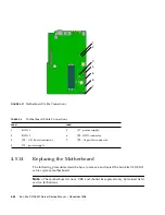
Страница 90: ... how to remove and install the Sun Fire X2100 M2 server system motherboard Note The motherboard is not a CRU and should be replaced only by trained field service technicians TABLE 4 3 Motherboard Cable Connections Label Label 1 SATA 1 5 J17 power supply 2 SATA 0 6 J29 ODD connector 3 JP5 I O board connector 7 JP8 16 pin fan connector 4 J13 power supply 3 4 6 7 5 1 2 ...

Страница 91: ...2 Replacing the PCIe Card and Riser Assembly on page 4 9 and the air duct see Section 4 5 6 Replacing an Air Duct on page 4 22 3 Disconnect all cables attached to the motherboard 4 Remove the four screws from the heatsink Note Do not remove the screws that secure the CPU heatsink assemblies mounting to the motherboard 5 Remove the five Phillips screws that fasten the motherboard to the chassis 6 R...

Страница 92: ...odules on page 4 31 4 5 14 2 Installing the Motherboard To install a motherboard Caution Observe proper ESD precautions in Section 4 2 1 ESD Precautions on page 4 2 when handling the new motherboard 1 Center the motherboard on the chassis so that the screw holes in the motherboard align with the screw holes on the chassis 2 Secure the five Phillips screws that fasten the motherboard to the chassis...

Страница 93: ... 12 Replacing a CPU and Heatsink on page 4 38 Section 4 5 10 Replacing Memory Modules on page 4 31 5 Replace the PCIe riser assembly and air baffle See Section 4 5 2 Replacing the PCIe Card and Riser Assembly on page 4 9 See Section 4 5 6 Replacing an Air Duct on page 4 22 6 Reconnect all internal system cables See Section 4 5 13 Replacing Cables on page 4 43 7 Replace the system cover 8 Replace a...

Страница 94: ...4 48 Sun Fire X2100 M2 Server Service Manual December 2006 ...

Страница 95: ...l as pinout information for the serial connector A 1 Physical Specifications TABLE A 1 lists the physical specifications for the Sun Fire X2100 M2 server TABLE A 1 Sun Fire X2100 M2 Server Physical Specifications Specification British Metric Width 16 8 inches 425 5 mm Depth 25 inches 633 7 mm Height 1 69 inches 43 mm Weight max 23 50 lbs 10 66 kg ...

Страница 96: ... Specification State British Metric Humidity Operating 7 93 RH non condensing 80 6 F max wet bulb 7 93 RH non condensing 38 C max wet bulb Nonoperating 93 RH non condensing 100 4 F max wet bulb 93 RH non condensing 43 C max wet bulb Vibration Operating 0 12 G x y 0 17 G z 5 500 Hz sine Nonoperating 0 3 G x y 0 6 G z 5 500 Hz sine Shock Operating 4 5 G to 3 5 G 11 msec half sine Temperature Operati...

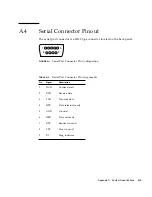
Страница 97: ... the back panel FIGURE A 1 Serial Port Connector Pin Configuration TABLE A 3 Serial Port Connector Pin Assignments Pin Signal Description 1 DCD Carrier detect 2 RXD Receive data 3 TXD Transmit data 4 DTR Data terminal ready 5 GND Ground 6 DSR Data set ready 7 RTS Request to send 8 CTS Clear to send 9 RI Ring indicator 5 1 9 6 ...

Страница 98: ...A 4 Sun Fire X2100 M2 Server Service Manual December 2006 ...

Страница 99: ... CD contains several software applications and utilities for use with your Sun Fire X2100 M2 server TABLE B 1 lists the contents of the CD and shows where to find more information on the contents TABLE B 1 Tools and Drivers CD Contents Application Document or Section in this Document Drivers and installation scripts for supported operating systems Sun Fire X2100 M2 Server Operating System Installa...

Страница 100: ...Reboot the server 3 When the Tools and Drivers CD menu is displayed select Upgrade System BIOS and SP firmware from the menu The BIOS and BMC will be updated to the latest versions and the system will automatically reboot The BIOS will automatically load the optimized defaults 4 Do the following after the firmware is updated Verify the BIOS settings Because the BIOS optimized defaults are automati...

Страница 101: ...n_guide sles_9_admin_guide pdf 2 Copy the combined BIOS BMC image from the remoteflash version bios_bmc_file file on the Tools and Drivers CD to your tftp server tftpboot directory Where version is the version of the Tools and Drivers CD that you are using and bios_bmc_file is the name of the BIOS BMC image For example remoteflash 1 0 90_3A02 3 Ensure that the OS on the platform is shut down 4 Log...

Страница 102: ... Out Manager Administration Guide for instructions on using the Embedded LOM web GUI getting image getting image successfully prepare to update Prepare OK starting update starting up ttys0 irq 1 i2c_eeprom_write 02 03 A0 0000 020C 64 0040 I2cMWrite 03 A0 0002 0040 SEEP Write offset 0 ok 64 0040 I2cMWrite 03 A0 0002 0040 SEEP Write offset 64 ok 64 0040 I2cMWrite 03 A0 0002 0040 SEEP Write offset 12...

Страница 103: ...rsion is the version of the Tools and Drivers CD that you are using and bios_bmc_file is the name of the BIOS BMC image For example remoteflash 1 0 90_3A02 3 Log in to the SP 4 Click on Control and select Firmware Update from the drop down menu The Firmware Update screen is displayed 5 Click Browse and navigate to the location of the flash file 6 Click Update The BIOS and BMC firmware on the Sun F...

Страница 104: ...he PXE Server You will need the following to set up the PXE server Red Hat kickstart server with a CD or DVD drive Instructions for setting up the Red Hat kickstart server can be found in the system administration guides for Red Hat Enterprise Linux Red Hat Enterprise Linux 3 manual at http www redhat com docs manuals enterprise RHEL 3 Manual sysadmin guide Red Hat Enterprise Linux 4 manual at htt...

Страница 105: ...erver and copy the boot img file located in the root directory of the CD to the new Sun Fire X2100 M2 server supplemental directory created in Step 3 5 Download the MEMDISK kernel a Go to the latest SYSLINUX project web site at http www kernel org pub linux utils boot syslinux b Save the latest syslinux version zip file to your root directory Where version is the latest SYSLINUX project version No...

Страница 106: ... the boot msg file 10 Edit the default PXE Configuration file as follows a Open the default file in a text editor b Type the following lines after the label0 section c Save and close the default file 11 Test the installation on the test machine cp syslinux 3 09 memdisk memdisk tftpboot linux install suppl_leo vi tftpboot linux install msgs boot msg suppl_leo Sun Fire X2100 M2 Server Tools and Driv...

Страница 107: ...Type suppl_leo at the prompt and press Return The MEMDISK kernel and the bootable portion of the Tools and Drivers CD are downloaded to the test machine over the network and into memory Once downloaded the bootable portion of the Tools and Drivers CD will be booted 6 The main menu of the bootable portion of the Tools and Drivers CD is displayed on the target Sun Fire X2100 M2 server 7 You can now ...

Страница 108: ...r the management software is installed you can run it as follows 5 Start Broadcom Broadcom Advanced Control Suite 2 Please note the following considerations when using the teaming feature of the Broadcom software Teaming two NVIDIA NICS or one NVIDIA NICS and one Broadcom NIC is not recommended but will work See FIGURE 1 2 for the location of the NVIDIA and Broadcom NICs One of the broadcom NICs i...

Страница 109: ...in front of front rack mounting plane at least 25 4 mm 1 inch Clearance depth to rear cabinet door behind front rack mounting plane at least 800 mm 31 5 inches with the cable management arm or 700 mm 27 5 inches without the cable management arm Clearance width between structural supports and cable troughs between front and rear mounting planes at least 456 mm 18 inches Caution Always load equipmen...

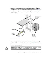
Страница 110: ...E C 1 3 Squeeze and hold the tabs at the top and bottom of the lock while you pull the mounting bracket out of the slide rail assembly until it reaches the stop See FIGURE C 1 4 Push the mounting bracket release button toward the front of the mounting bracket as shown in FIGURE C 1 and simultaneously withdraw the mounting bracket from the slide rail assembly 5 Repeat for the remaining slide rail a...

Страница 111: ...pins on the side of the chassis FIGURE C 2 Aligning the Mounting Bracket With the Server Chassis 2 With the heads of the three chassis locating pins protruding though the three keyed openings in the mounting bracket pull the mounting bracket toward the front of the chassis until the mounting bracket clip locks into place with an audible click See FIGURE C 2 3 Verify that the rear locating pin has ...

Страница 112: ... the screws completely The method used to attach the slide rails varies depending on the type of rack If your rack has threaded mounting holes in the rack posts first determine whether the threads are metric or standard then insert the correct mounting screws through the slide rail brackets and into the threaded holes If your rack does not have threaded mounting holes insert the mounting screws th...

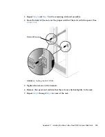
Страница 113: ...rail assembly 4 From the front of the rack set the proper width of the rails with the spacer See FIGURE C 4 FIGURE C 4 Setting the Rail Width 5 Tighten the screws on the brackets 6 Remove the spacer and confirm that the rails are attached tightly to the rack 7 Repeat Step 4 through Step 6 for rear of the rack Rail width spacer ...

Страница 114: ...emblies Use this procedure to install the server chassis with mounting brackets into the slide rail assemblies that are mounted to the rack Caution This procedure requires a minimum of two people because of the weight of the server Attempting this procedure alone could result in equipment damage or personal injury Caution Always load equipment into a rack from the bottom up so that it will not bec...

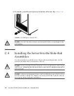
Страница 115: ...pproximately 12 inches or 30 cm FIGURE C 6 Inserting the Server With Mounting Brackets Into the Slide Rails 4 Simultaneously push and hold the slide rail release buttons on each mounting bracket while you push the server into the rack See FIGURE C 6 Continue pushing until the slide rail locks on the front of the mounting brackets engage the slide rail assemblies You will hear an audible click Caut...

Страница 116: ...quate room to work around the back of the server Note References to left or right in this procedure assume that you are facing the back of the equipment rack 3 Locate the CMA rail extension and insert it into the left slide rail until the extension locks into place with an audible click See FIGURE C 7 The CMA rail extension might be taped to the CMA assembly FIGURE C 7 Inserting the CMA Rail Exten...

Страница 117: ...ges the slide rail as shown in FIGURE C 8 FIGURE C 8 Detail of CMA Rail Extension Inserted Into the Left Slide Rail Note Support the CMA in the remaining installation steps Do not allow the assembly to hang by its own weight until it is secured by all three of the attachment points CMA rail extension Left slide rail ...

Страница 118: ...nsert the CMA s mounting bracket connector into the right slide rail until the connector locks into place with an audible click See FIGURE C 9 FIGURE C 9 Inserting the CMA Mounting Bracket Into the Back of the Right Slide Rail Right slide rail CMA mounting bracket ...

Страница 119: ...rt the right CMA slide rail connector into the right slide rail assembly until the connector locks into place with an audible click See FIGURE C 10 FIGURE C 10 Inserting CMA Slide Rail Connector Into Back of Right Slide Rail Assembly CMA slide rail connector Right slide rail assembly ...

Страница 120: ...ft CMA slide rail connector into the rail extension on the left slide rail assembly until the connector locks into place with an audible click See FIGURE C 11 FIGURE C 11 Connecting the CMA Arm to Rail Extension Connector CMA extension CMA arm connector on left slide rail arm ...

Страница 121: ...s in the CMA and snap them into place See FIGURE C 12 For best results place three hangers evenly spaced on the rear facing side of the CMA and three on the side facing the server FIGURE C 12 Installing CMA Cable Hangers 9 Install cables to your server as required 10 Route the cables through the CMA cable hangers CMA arm CMA cable hanger ...

Страница 122: ...e server is fully extended you must release two sets of slide rail stops to return the server to the rack a The first set of stops are levers located on the inside of each slide rail just behind the back panel of the server These levers are labeled PUSH Push in both levers simultaneously and slide the server toward the rack The server will slide in approximately 15 inches 38 cm and stop Verify tha...

Страница 123: ...Appendix C Installing the Server Into a Rack With Optional Slide Rails C 15 ...

Страница 124: ...C 16 Sun Fire X2100 M2 Server Service Manual December 2006 ...

Страница 125: ...D or DVD problems troubleshooting 2 4 CMA assembly C 9 components orderable 1 10 replacement procedures 4 6 cover removal 4 3 CPU location 1 7 4 5 replacing 4 38 specifications 1 2 customer orderable components 1 10 customer replaceable unit replacement procedures 4 6 D depth of system A 1 diagnostic partition accessing Red Hat Linux 3 13 Solaris 10 3 15 Windows XP 3 16 adding 3 12 log file 3 12 r...

Страница 126: ...n ESD precautions 4 2 postinstallation instructions 4 3 precautions 4 2 preinstallation instructions 4 2 installing to a rack C 1 internal components 1 7 4 5 J Java Enterprise System 1 3 K keyboard troubleshooting 2 5 L list of customer replaceable units CRUs 4 6 M maintenance procedures ESD precautions 4 2 postinstallation precautions 4 3 preinstallation instructions 4 2 memory modules location 1...

Страница 127: ...ication button 1 5 system identification LED 1 5 1 6 system management software 1 4 system specifications environmental A 2 physical A 1 power A 2 T temperature specifications A 2 Tools and Drivers CD BIOS and BMC firware update B 2 booting from a PXE server B 6 Broadcom NetXtreme software B 9 software overview 1 4 tools for maintenance procedures 4 1 troubleshooting CD or DVD media 2 5 CD or DVD ...

Страница 128: ...Index 4 Sun Fire X2100 M2 Server Service Manual December 2006 ...
Отзывы: