background image

Chapter 4

Rackmount Installation

4-5

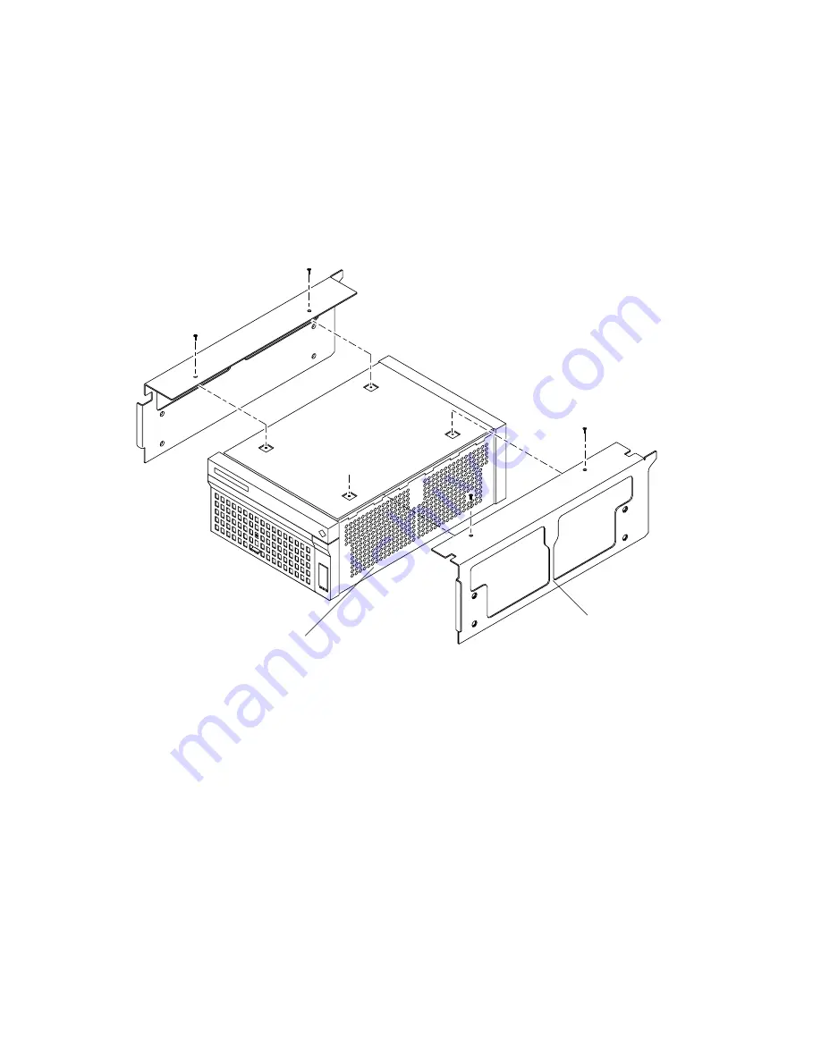
3. Place the baseplate on the chassis.

For disk arrays being installed in a Sun StorEdge Expansion Cabinet, use the
two-part baseplate (

FIGURE 4-3

).

Make sure that the vented baseplate is installed on the exhaust side of the disk array.

FIGURE 4-3

Baseplate for Sun StorEdge Expansion Cabinet

Exhaust side

Vented baseplate

Содержание STOREDGE A5000

Страница 1: ...31 Sun StorEdge A5000 Installation and Service Manual Includes the Entire Series of StorEdge A5000 Disk Arrays Formerly the Sun Enterprise Network Array Part No 802 7573 16 September 1999 Revision A S...

Страница 2: ...t 1999 Sun Microsystems Inc 901 San Antonio Road Palo Alto CA 94303 Etatis Unis Tous droits r serv s Ce produit ou document est prot g par un copyright et distribu avec des licences qui en restreignen...

Страница 3: ...erate this equipment FCC Class B Notice This device complies with Part 15 of the FCC Rules Operation is subject to the following two conditions 1 This device may not cause harmful interference 2 This...

Страница 4: ...exigences du R glement sur le mat riel brouilleur du Canada DOC Class B Notice Avis DOC Classe B This Class B digital apparatus meets all requirements of the Canadian Interference Causing Equipment Re...

Страница 5: ...roduct Placement of a Sun Product Caution Do not block or cover the openings of your Sun product Never place a Sun product near a radiator or heat register Failure to follow these guidelines can cause...

Страница 6: ...mperatur Nicht ber hren da Verletzungsgefahr durch hei e Oberfl che besteht Achtung Gef hrliche Spannungen Anweisungen befolgen um Stromschl ge und Verletzungen zu vermeiden Ein Setzt das System unter...

Страница 7: ...texte traite des mesures de s curit qu il convient de prendre pour l installation d un produit Sun Microsystems Mesures de s curit Pour votre protection veuillez prendre les pr cautions suivantes pen...

Страница 8: ...e terre Pour carter tout risque d lectrocution branchez toujours ce cordon dans une prise mise la terre L avertissement suivant s applique uniquement aux syst mes quip s d un interrupteur VEILLEUSE At...

Страница 9: ...trada salida cumple los requisitos de la normativa SELV Conexi n del cable de alimentaci n el ctrica Precauci n Los productos Sun est n dise ados para trabajar en una red el ctrica monof sica con toma...

Страница 10: ...de no tener en cuenta esta precauci n puede ocasionar da os personales o perjudicar el funcionamiento del equipo Aviso de cumplimiento con requisitos de l ser Los productos Sun que utilizan la tecnolo...

Страница 11: ...with the following requirements of the Low Voltage Directive 73 23 EEC EC Type Examination Certificates EN60950 IEC950 EN60950 w Nordic Deviations Supplementary Information This product was tested an...

Страница 12: ...xii Sun StorEdge A5000 Installation and Service Manual September 1999...

Страница 13: ...uirements 2 2 2 2 Placement 2 2 2 3 Inspecting the Disk Array 2 3 2 4 Installing the Disk Array 2 3 2 4 1 Connecting the Power Cord 2 3 2 4 2 Installing Additional Interface Boards and GBICs 2 4 2 4 3...

Страница 14: ...embling the Cabinet 4 12 5 FPM Screens 5 1 5 1 Differences Between 14 Slot and 22 Slot Disk Arrays 5 2 5 2 FPM Main Screens 5 3 5 3 Menu and Level 2 Status Screens 5 4 5 4 Power Supplies 5 5 5 5 Set U...

Страница 15: ...Power Filter 7 16 7 2 10 Backplane 7 17 7 2 11 Interconnect Assembly 7 19 7 2 12 Removing a Rackmounted Disk Array 7 26 8 Software Firmware and FCode Packages 8 1 8 1 Solaris Release and Installed Pat...

Страница 16: ...Clearance B 3 B 3 Electrical Specifications B 3 B 4 Environmental Specifications B 4 C Disk Replacement Using Solstice DiskSuite C 1 D Firmware and Device Driver Error Messages D 1 D 1 Target Numbers...

Страница 17: ...Contents xvii D 6 2 sf Driver Software Errors D 15...

Страница 18: ...xviii Sun StorEdge A5000 Installation and Service Manual September 1999...

Страница 19: ...4 3 FIGURE 4 2 Removing the Feet 4 4 FIGURE 4 3 Baseplate for Sun StorEdge Expansion Cabinet 4 5 FIGURE 4 4 Baseplate for Other Cabinets 4 6 FIGURE 4 5 Threading Screws Into the Cabinet 4 7 FIGURE 4...

Страница 20: ...Door 7 12 FIGURE 7 8 Removing the Screws From the Door Panel Assembly 7 12 FIGURE 7 9 Removing a Door Panel Assembly 7 13 FIGURE 7 10 Removing the FPM 7 13 FIGURE 7 11 Removing a Fan Tray 7 14 FIGURE...

Страница 21: ...gures xxi FIGURE 7 23 Removing the Chassis and Baseplate From the Cabinet 7 27 FIGURE 7 24 Removing the Baseplate From the Chassis 7 28 FIGURE 8 1 Opening a Door C 3 FIGURE 8 2 Removing a Disk Drive C...

Страница 22: ...xxii Sun StorEdge A5000 Installation and Service Manual September 1999...

Страница 23: ...r trained service provider Using UNIX Commands This document does not contain information on basic UNIX commands and procedures such as shutting down the system booting the system and configuring devi...

Страница 24: ...have mail AaBbCc123 What you type when contrasted with on screen computer output su Password AaBbCc123 Book titles new words or terms words to be emphasized Command line variable replace with a real n...

Страница 25: ...les you to access Sun technical documentation on the Web You can browse the docs sun com archive or search for a specific book title or subject at http docs sun com Sun Welcomes Your Comments We are i...

Страница 26: ...xxvi Sun StorEdge A5000 Installation and Service Manual September 1999...

Страница 27: ...nclosure to be displayed and modified Active components in the disk array are redundant and can be replaced while the disk array is operating Caution If over half of the disk drive bays are loaded and...

Страница 28: ...RE 1 1 and FIGURE 1 2 show and TABLE 1 1 describes the front components FIGURE 1 1 Front Components 14 slot FIGURE 1 2 Front Components 22 slot FPM Front fan tray Power supply 2 Power supply 0 Disk dr...

Страница 29: ...ector specification Dual 100 Mbytes sec FC AL ports on each drive Power supplies Takes AC power from the interconnect board and supplies DC voltages of 5 3 3 and 12 volts to a common power circuit FPM...

Страница 30: ...e rear components FIGURE 1 3 Rear Components 14 slot FIGURE 1 4 Rear Components 22 slot Rear fan tray AC power filter Interface board A Disk drive 0 Power supply 1 Disk drive 6 Interface board B GBIC...

Страница 31: ...ive Interface boards Provides all intelligent controls in the enclosure sensing and setting the environmental service signals as required by conditions inside the enclosure The interface board receive...

Страница 32: ...5 Internal Components TABLE 1 3 Internal Components Component Description Interconnect assembly Routes power control sense and Fibre Channel signals between internal components Backplanes Routes powe...

Страница 33: ...chapter describes how to install a disk array in a tabletop configuration This chapter contains the following topics Electrical Requirements page 2 2 Placement page 2 2 Inspecting the Disk Array page...

Страница 34: ...up to 120 pounds 54 kg The disk array is designed to sit on a desk or table Use the following guidelines to prepare a location for your system Choose a desk or table that can support up to 120 pounds...

Страница 35: ...e use 2 4 Installing the Disk Array Installing the disk array involves connecting the power cord adding additional interface boards and GBICs if needed and routing the fiber optic cables Read this sec...

Страница 36: ...to install an additional interface board see Section 7 2 4 Interface Board on page 7 11 2 4 3 Connecting Fiber Optic Cables 1 Power on the disk array 2 Remove the covers from the connectors of the fib...

Страница 37: ...ly be installed as shown in FIGURE 2 2 FIGURE 2 2 GBIC on the Rear Panel 6 Connect the other end of the fiber optic cable to the other device that will be connected to the disk array Refer to the Sun...

Страница 38: ...2 6 Sun StorEdge A5000 Installation and Service Manual September 1999...

Страница 39: ...prise 4x00 system For mounting instructions refer to the Sun Enterprise Caster Base Installation Guide part number 802 5034 For cabling instructions see Chapter 2 Note The only supported configuration...

Страница 40: ...3 2 Sun StorEdge A5000 Installation and Service Manual September 1999...

Страница 41: ...This chapter describes how to install a disk array in system or expansion cabinets This chapter contains the following topics Preparing the Disk Array page 4 2 Installing the Rails page 4 7 Installing...

Страница 42: ...ontact your service provider Note Retrieve the placement information for the disk array before beginning the installation 4 2 Preparing the Disk Array To install a tabletop version of the disk array i...

Страница 43: ...three screws from a side panel FIGURE 4 1 FIGURE 4 1 Removing the Side Panels 2 Pull the panel away from of the chassis and set it aside 3 Repeat to remove the remaining side panel Note The plastic pa...

Страница 44: ...to the chassis underside Note The Sun StorEdge Expansion Cabinet uses a two part baseplate Other system and expansion cabinets use a solid baseplate 1 With the aid of an assistant invert the chassis...

Страница 45: ...r disk arrays being installed in a Sun StorEdge Expansion Cabinet use the two part baseplate FIGURE 4 3 Make sure that the vented baseplate is installed on the exhaust side of the disk array FIGURE 4...

Страница 46: ...on cabinets use the solid baseplate FIGURE 4 4 FIGURE 4 4 Baseplate for Other Cabinets 4 Loosely thread the four short screws you removed from the feet into all four holes When all screws are started...

Страница 47: ...om screws on the left side of the cabinet FIGURE 4 5 Install the screws as specified in the online Rackmount Placement Matrix FIGURE 4 5 Threading Screws Into the Cabinet 2 Place the left side rail in...

Страница 48: ...egs can result in the cabinet tipping forward and injuring personnel Caution This installation requires two people to lift and move the disk array Use care to avoid injury A disk array with a baseplat...

Страница 49: ...binet FIGURE 4 7 FIGURE 4 7 Installing Screws to Secure the Baseplate to the Side Brackets 4 4 1 Connecting the Power Cable 1 Connect the female end of the power cord to the power receptacle at the re...

Страница 50: ...the Sun StorEdge A5000 Hardware Configuration Guide part number 805 0264 4 Secure the extra length of the power cord near the power distribution unit 4 4 2 Installing Additional Interface Boards and G...

Страница 51: ...onnect one end of the fiber optic cable to the GBIC FIGURE 4 9 Note Fiber optic cable connectors are keyed to prevent improper insertion they can be installed only as shown in FIGURE 4 9 FIGURE 4 9 GB...

Страница 52: ...4 Reassembling the Cabinet Follow the instructions on preparing for service in your system or expansion cabinet documentation If necessary be sure to Replace or close the top front panel Replace or c...

Страница 53: ...lot Disk Arrays page 5 2 FPM Main Screens page 5 3 Menu and Level 2 Status Screens page 5 4 Power Supplies page 5 5 Set Up 1 page 5 6 Set Up 2 page 5 7 Test Screen page 5 8 Disk Drives page 5 9 Backpl...

Страница 54: ...y Except for the number of disk drives and nodes the screens for the 14 slot disk array and the 22 slot disk array are the same The disk view front drive rear drive and nodes screens for the 22 slot d...

Страница 55: ...n level 1 screens on the disk array are the disk view and menu screens FIGURE 5 2 Press the buttons in the lower right corners of these screens to toggle between them FIGURE 5 2 Level 1 Screens Disk v...

Страница 56: ...n and Service Manual September 1999 5 3 Menu and Level 2 Status Screens System Box status name Note If there is a FRU failure the icon for the failed device will be in reverse display and the caution...

Страница 57: ...ertemp OK To next power supply Disk view If a power supply is not installed then the button for that device on the L2 status screen will be empty The L3 status screen will display Not Present Power Fa...

Страница 58: ...aver from activating press the screen saver button Set up screen You can enter multiple changes at the same time on the Set Up screen For instance if you want to change the Loop Type and Box ID set th...

Страница 59: ...nfirm screen Cancel by pressing the Cancel key Nodes screen This screen lists the number of active nodes per loop This number includes the host GBICs interface board GBICs and disk drive connections T...

Страница 60: ...eg Displays the value of some key FC AL SOC status registers The value of the registers are updated a couple of times per second 8 Autobypass Systematically bypasses all of the failing elements on a l...

Страница 61: ...Drive Disk view To next disk drive Disk View Back screen number 0 6 Confirm screen The front and rear drives use similar screens To install or replace a disk drive see Section 7 2 1 Disk Drive on page...

Страница 62: ...screen Temperature Backplane On Off Back screen To replace a backplane see Section 7 2 10 Backplane on page 7 17 FRU revision Disk view To next backplane On Off button Bypass Port The buttons on this...

Страница 63: ...ken1 Signal Receiver status there is light but no sync bad signal The host adapter or hub or a GBIC in either may be broken1 No Signal Receiver status no signal A GBIC in the host adapter hub or inter...

Страница 64: ...ber 1999 5 11 Fan Trays To next fan tray Disk view Disk view Critical Status OK failed Disk fan status OK failed Power supply fan status OK failed Back screen To replace a fan tray see Section 7 2 7 F...

Страница 65: ...ate that interface boards Flashing icon indicates a system error Go to menu screen to determine FRU group failure Connected to Loops A and B Connected to Loop A Connected to Loop B Not connected Disk...

Страница 66: ...mber 1999 5 13 Interface Boards To next interface board Disk view Disk View Soft reset button Board status OK Failed Firmware revision Temperature overtemp OK Back screen To replace an interface board...

Страница 67: ...he checksum is incorrect Replace the interconnect assembly Ok The EEPROM has a magic word and it has the correct checksum Fail The interconnect assembly is broken Replace the interconnect assembly Dis...

Страница 68: ...5 16 Sun StorEdge A5000 Installation and Service Manual September 1999...

Страница 69: ...6 5 Power Supply page 6 6 Disk Drive page 6 7 Note When the amber fault LED is lit for a field replaceable unit FRU the FRU most likely needs to be replaced The state of the other LEDs associated wit...

Страница 70: ...tember 1999 6 1 Location of LED Indicators FIGURE 6 1 Front Panel LEDs FIGURE 6 2 Rear Panel LEDs Enclosure Fan tray Power supply Power supply Disk drive LEDs LEDs LEDs LEDs LEDs Enclosure Disk drive...

Страница 71: ...unbroken Verify link source is operating N A Fault in GBIC Replace GBIC See Section 7 2 3 GBIC on page 7 9 GBIC not installed No power to GBIC GBIC is incompletely inserted Install GBIC if required V...

Страница 72: ...LEDs TABLE 6 3 Fan Tray LEDs Ready Fault Indication Corrective Action Okay None N A Fault condition Replace the fan tray See Section 7 2 7 Fan Tray on page 7 14 Fan tray is turned off Fan tray is imp...

Страница 73: ...n tray FIGURE 6 5 Enclosure LEDs TABLE 6 4 Enclosure LEDs Power Fault Ready Indication Corrective Action Power is on None System is ready None System is active None N A N A A FRU has failed Use the FP...

Страница 74: ...Supply LEDs Ready Fault Indication Corrective Action Okay None Fault condition Replace the power supply See Section 7 2 8 Power Supply on page 7 15 The power supply is not installed The power supply...

Страница 75: ...is identified and disk drive can be inserted or removed Insert or remove the disk drive N A Fault condition Replace disk drive See Section 7 2 1 Disk Drive on page 7 3 The disk drive is not installed...

Страница 76: ...6 8 Sun StorEdge A5000 Installation and Service Manual September 1999...

Страница 77: ...em for service according to the instructions given there Note All items in this chapter are hot pluggable except for the AC filter module the disk drive backplanes and the interconnect assembly This c...

Страница 78: ...FRU that is not hot pluggable the AC filter module the disk drive backplane or the interconnect assembly then you will also need to Power off the disk array Caution To avoid possible cooling issues ha...

Страница 79: ...e the luxadm insert_device command to install the new disk on each host Notify the software of the new disk Note For a disk in a multihost environment the disk replacement procedure should first be pe...

Страница 80: ...the luxadm remove_device F option for example luxadm remove_device F box2 r0 may be required Make sure you have stopped all I O to the disk drive before using the F option Refer to the luxadm man pag...

Страница 81: ...e door FIGURE 7 1 FIGURE 7 1 Opening a Door 5 Remove the disk drive FIGURE 7 2 Push down on the latch to release the bracket handle Use the handle to pull the disk drive out of the slot FIGURE 7 2 Rem...

Страница 82: ...released Once you have inserted the disk drive as far as it will go into the slot push down on the handle to secure it Note For arrays under volume manager or other RAID manager control the new disk...

Страница 83: ...manager of the new disk For example 13 Use the vxdiskadm command to bring the new disk into volume manager control Note To replace a disk drive choose option 5 To add a disk drive choose option 1 Add...

Страница 84: ...ctors when the cable is disconnected Note Dirty fiber optic cable connectors can impeded data transfer Before replacing a fiber optic cable be sure that the connectors on the cable are clean Disconnec...

Страница 85: ...7 2 2 2 Remove the GBIC Sun currently ships two types of GBICs one with a bailed locking mechanism and one without To remove a GBIC that does not have a bail push the module tabs together and pull the...

Страница 86: ...3 Replace the GBIC To insert a GBIC that does not have a bail slide the GBIC into the port until you hear a click Be sure that both tabs on the left and right sides of the GBIC have engaged To insert...

Страница 87: ...the spacer and install the interface board FIGURE 7 6 1 Disconnect the fiber optic cable s see Section 7 2 2 2 Use a Phillips screwdriver to remove the screws 3 Remove the interface board FIGURE 7 6...

Страница 88: ...is the same for removing the front or rear door assemblies 1 Remove the door FIGURE 7 7 Rotate the door down about 30 degrees and lift it off the hinges FIGURE 7 7 Removing a Door 2 Remove the three s...

Страница 89: ...URE 7 9 FIGURE 7 9 Removing a Door Panel Assembly 4 Reverse these steps to reinstall the door panel assembly 7 2 6 FPM 1 Remove the front door and panel assembly see Section 7 2 5 2 Remove the four sc...

Страница 90: ...7 Fan Tray Caution The disk array can only operate for up to 2 minutes with one functioning fan tray 1 Remove the door and panel assembly see Section 7 2 5 2 Use the Phillips screwdriver to remove th...

Страница 91: ...array may power off 1 Remove the door and panel assembly see Section 7 2 5 2 Use the Phillips screwdriver to remove the screws FIGURE 7 12 Note If you are installing an additional power supply use a P...

Страница 92: ...AC filter module 1 Power off the disk array 2 Disconnect the power cable 3 Remove the rear door and panel assembly see Section 7 2 5 4 Use the Phillips screwdriver to remove the retaining screw from t...

Страница 93: ...array before replacing the disk drive backplane 1 Power off the disk array 2 Disconnect the power cable 3 Remove the disk drives see Section 7 2 1 4 Remove the door and panel assembly see Section 7 2...

Страница 94: ...ber 1999 6 Remove the lower disk drive guides FIGURE 7 15 FIGURE 7 15 Removing the Lower Disk Drive Guides 7 Use a Phillips screwdriver to remove the screws securing the disk drive backplane FIGURE 7...

Страница 95: ...ge 7 26 for removal instructions Caution The interconnect assembly is not a hot plug item You must remove power to the disk array before replacing the interconnect assembly The disk array interconnect...

Страница 96: ...hit Return until the following step has been completed 3 Power off the disk array luxadm remove_device box2 WARNING Please ensure that no filesystems are mounted on these device s All data on these de...

Страница 97: ...ection 7 2 5 Door Panel Assembly on page 7 12 Section 7 2 7 Fan Tray on page 7 14 Section 7 2 8 Power Supply on page 7 15 Section 7 2 9 AC Power Filter on page 7 16 Section 7 2 10 Backplane on page 7...

Страница 98: ...ual September 1999 6 Remove the side panels FIGURE 7 18 FIGURE 7 18 Removing the Side Panels 7 Remove the top panel FIGURE 7 19 Lift up on the front edges of the top panel while an assistant pushes it...

Страница 99: ...Chapter 7 Service 7 23 8 Use a Phillips screwdriver to remove the screws securing the metal access plate FIGURE 7 20 FIGURE 7 20 Removing the Metal Access Plate 9 Remove the metal access plate...

Страница 100: ...four screws holding the assembly See FIGURE 7 21 b Lift the assembly and set it aside FIGURE 7 21 Removing the Interconnect Assembly 11 Reverse Step 5 through Step 9 to reassemble the disk array 12 Po...

Страница 101: ...s and ses paths with the new WWN For example luxadm insert_device Please hit enter when you have finished adding photon s Waiting for Loop Initialization to complete New Logical Nodes under dev es ses...

Страница 102: ...nstructions on preparing for service in your system or expansion cabinet documentation If necessary be sure to Extend the antitilt bar Remove or open the top front panel 1 Power off the disk array 2 D...

Страница 103: ...s stopped by the tabs on the side rails in the cabinet FIGURE 7 23 FIGURE 7 23 Removing the Chassis and Baseplate From the Cabinet 6 With the aid of an assistant one person on each side tilt the front...

Страница 104: ...late 1 With the aid of an assistant invert the chassis with the front facing you FIGURE 7 24 2 Use a No 1 Phillips screwdriver to remove the screws that secure the baseplate to the chassis FIGURE 7 24...

Страница 105: ...s how to check and upgrade where appropriate the various software firmware and FCode packages used with the disk array Solaris Release and Installed Patches page 8 2 Host Adapter and I O Board FCode p...

Страница 106: ...resent on systems running the Solaris 2 5 1 operating environment or previous releases 8 1 2 Checking for an Installed Patch To check for an installed patch use the showrev p command and grep for the...

Страница 107: ...k for the boot message in the var adm messages file For example 8 2 3 Checking FCode on the I O Board To check the FCode version on the I O board run the usr platform sun4u sbin prtdiag v command and...

Страница 108: ...truction luxadm fcal_s_download f usr lib firmware fc_s fcal_s_fcode Found Path to 1 FC100 S Cards Device devices io unit f e0200000 sbi 0 0 SUNW socal 2 0 WARNING This program will update the Fcode i...

Страница 109: ...e IB has a newer revision of firmware This protects against the disk array ever running different versions in the two IBs 8 3 1 Checking IB Firmware When you replace an IB or an interconnect assembly...

Страница 110: ...de from revision 1 01 to 1 05 or later versions of the firmware For example if you have an disk array running 1 01 and the current patch firmware is 1 07 you will need to upgrade to 1 03 and then to 1...

Страница 111: ...aths to the disks and grep for Revision For example The first two characters are the revision the last are a vendor hardware HW code For instructions on upgrading disk drive firmware read the README t...

Страница 112: ...8 8 Sun StorEdge A5000 Installation and Service Manual September 1999...

Страница 113: ...NDIX A Parts Breakdown The disk array components listed in this appendix can be replaced at the customer site by a qualified service provider or by a user For removal and replacement procedures see Ch...

Страница 114: ...3852 Disk drive assembly 1 6 inch 540 2877 Disk guide kit 1 6 inch 501 4372 7 slot disk drive backplane 540 2864 Interconnect assembly 300 1295 Power supply TABLE A 2 Rear FRUs Part Number Description...

Страница 115: ...ive assembly 1 inch 540 2879 Disk guide kit 1 inch 501 4158 11 slot disk drive backplane 540 2864 Interconnect assembly 300 1295 Power supply TABLE A 4 Rear FRUs Part Number Description 540 2859 Rear...

Страница 116: ...A 4 Sun StorEdge A5000 Installation and Service Manual September 1999...

Страница 117: ...ons This appendix describes the following specifications of the disk array Physical Specifications page B 2 Service Access and Airflow Clearance page B 3 Electrical Specifications page B 3 Environment...

Страница 118: ...h high disk drives 3 Max numbers are with fourteen 1 6 inch high disk drives 4 This weight includes the mounting tray The mounting tray can weigh up to 15 pounds 6 8 kg TABLE B 2 Physical Specificatio...

Страница 119: ...dge Expansion Cabinet with Sun StorEdge A5000 disk arrays installed requires at least a two inch clearance on the exhaust vented side of the expansion cabinet to maintain proper airflow B 3 Electrical...

Страница 120: ...ABLE B 4 Environmental Specifications Parameter Operating Non Operating Temperature 5 C to 40 C ambient 20 C to 60 C ambient Humidity 20 to 80 RH noncondensing 93 RH Altitude 3 km 12 km Vibration 0 2G...

Страница 121: ...the disk label if multiple slices on the disk drive are being used Perform this step if you are using a slice other than s2 See the prtvtoc man page for more information 2 Use the metareplace command...

Страница 122: ...ve should also be blinking Note Do not hit Return until Step 4 and Step 5 have been completed luxadm remove F dev rdsk c2t17d0s2 WARNING Please ensure that no filesystems are mounted on these device s...

Страница 123: ...ite C 3 4 Open the door FIGURE 8 1 FIGURE 8 1 Opening a Door 5 Remove the disk drive FIGURE 8 2 Push down on the latch to release the bracket handle Use the handle to pull the disk drive out of the sl...

Страница 124: ...Logical Nodes Removing c1t17d0s0 Removing c1t17d0s1 Removing c1t17d0s2 Removing c1t17d0s3 Removing c1t17d0s4 Removing c1t17d0s5 Removing c1t17d0s6 Removing c1t17d0s7 Removing c2t17d0s0 Removing c2t17d...

Страница 125: ...h down on the handle to secure it Note The FPM icon for the disk drive you replaced should be lit In addition the green LED under the disk drive should be blinking Hit Return after inserting the devic...

Страница 126: ...nd press firmly 11 Restore the disk label if you saved it in Step 1 12 Replace metdb if needed See the metadb man page for more information 13 Enable new disk slices with the metareplace e command See...

Страница 127: ...rage Array This appendix does not include error messages generated by Solstice DiskSuite software D 1 Target Numbers The target number is the hexadecimal value for the physical target of the device th...

Страница 128: ...ace board Decoding the example of 00110011 yields the following results TABLE D 1 Target Numbers Bits Description 0 Not used 1 2 The Box ID 0 through 3 3 Backplane 0 for front 1 for rear 4 7 The locat...

Страница 129: ...producer and its severity For example The messages in this appendix are shown with the message ID and the message text even though the message ID is not displayed on the console The character stands...

Страница 130: ...n also be caused by an unsupported configuration When these errors occur the host adapter s associated with these messages will not be functional socal attach 4003 socal attach failed alloc soft state...

Страница 131: ...rted The above message is displayed only if the socal driver was forced into a reset condition and failed to restart This indicates of a system resource kernel memory problem socal driver 4020 socal a...

Страница 132: ...emoval of a node In either case the sf structure that is being detached is invalid When this occurs the disk array associated with this message will not be functional sf failed to allocate soft state...

Страница 133: ...op when a pre existing device with the same ID already exists When this error occurs the device associated with this messages will not be functional The above message is displayed if the sf driver sen...

Страница 134: ...components D 4 1 socal Driver Hardware Errors The above message may be displayed if no date code is present in the host adapter microcode This situation should not occur under normal circumstances an...

Страница 135: ...above messages indicate the presence of invalid fields in the Fibre Channel frames received by the host adapter This may indicate a non Sun Fibre Channel device in the Fibre Channel loop of a disk arr...

Страница 136: ...e 0x x sf Target 0x x Reset Failed Ret x sf Target 0x x Reset failed Abort Failed sf Transport error on cmd x target 0x x s FCP_RSP FCP_CMND fields invalid FCP_RSP Task Management Function Not Support...

Страница 137: ...should take to fix the problem This message means that the host adapter has failed and needs to be replaced as soon as possible The above message indicates an Extended Loop Services ELS has encountere...

Страница 138: ...om the firmware This is usually caused by a failed LIP or certain devices on the loop that do not properly respond to report loop position depending on the status D 5 Informational Messages Messages i...

Страница 139: ...a host adapter a hub or a disk array Fiber optic cable Interface board Host adapter Following a link OFFLINE any pending I O operations to the disk array will be held by the driver for about one to tw...

Страница 140: ...entioned above The most likely cause of the other message is the offlining of a target most likely a disk that requires a reset of the loop The target associated with this message will not be function...

Страница 141: ...hardware usually either the disk array host adapter or SBus hardware The errors do not normally occur under normal operation D 6 1 socal Driver Software Errors The above message indicates a hardware...

Страница 142: ...The above message indicates that some DDI routine tried to prepare a packet for DMA or make certain DMA has completed on the packet and the operation failed It is difficult to determine under what ci...

Страница 143: ...8 7 FCode 8 3 IB firmware 8 5 patch 8 2 Solaris release 8 2 clearance service access and airflow B 3 components front 1 2 internal 1 6 rear 1 4 confirm screen 5 7 connecting fiber optic cable 4 10 po...

Страница 144: ...nel module FPM 5 3 location 1 3 replacing 7 13 G gigabit interface converter GBIC installing 7 9 LED 6 3 location 1 5 replacing 7 9 screen 5 11 I informational messages sf driver D 14 socal driver D 1...

Страница 145: ...0 confirm 5 6 5 7 5 9 5 10 5 11 5 12 5 14 disk drive 5 9 disk view 5 13 fan tray 5 12 gigabit interface converter GBIC 5 11 interconnect assembly 5 15 interface board 5 14 name 5 7 nodes 5 7 power sup...

Страница 146: ...Index 4 Sun StorEdge A5000 Installation and Service Manual September 1999...

Отзывы: