1-10
PCI I/O Board Installation and Component Replacement • February 1998
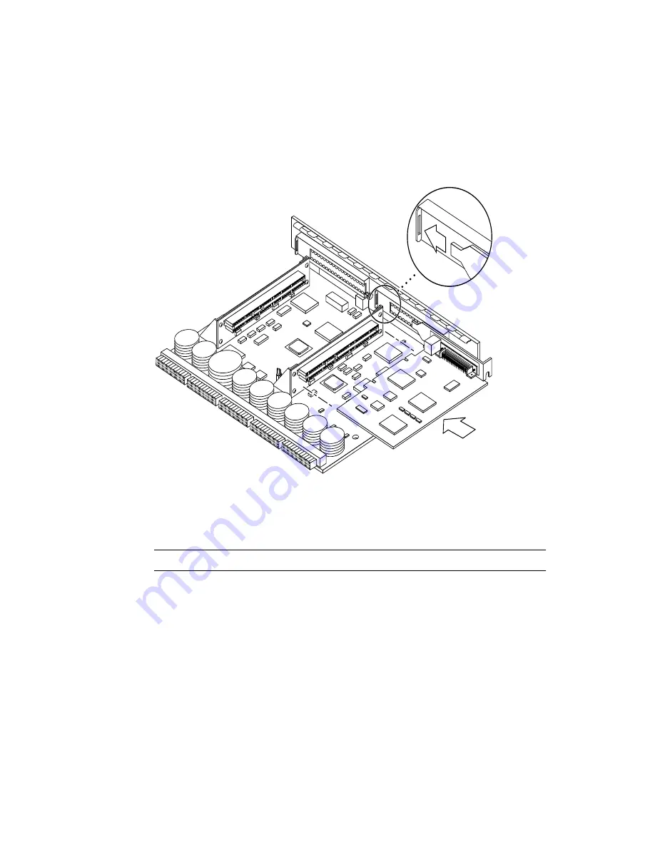
3. Align the PCI card so that the connector mates with the PCI board connector.
Make sure that the right rear of the card is retained by the opening in the metal catch
mechanism (
) and the front right is aligned to accept the locking
thumbscrew (
FIGURE 1-7
PCI card installation/replacement
4. Once the card is properly positioned (as described in Step 3) and seated properly
to the connector on the PCI board, tighten the locking thumbscrew.
Note –
Some PCI cards may not require the standoff for mounting.
5. If the standoff is required ensure that the standoff is positioned to capture the
edge of the PCI card, and then tighten the screw securing the standoff.
6. Use the procedures in the Section 1.5.2 “Installing a PCI I/O Board” on page 1-5, to
replace the PCI I/O board.
Catch mechanism
detail


