


Installation
29
Remote On/Off Cable (Optional Accessory)
A remote on/off cable can be furnished as an accessory. See the Parts section for part number
and ordering.
1.
Disconnect the power to the compressor.
2.
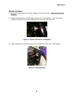
Remove the heat shrink cap from one end of the remote on/off cable. Connect the cable to
customer’s remote switch. Use the green conductor to ground the switch box. Switch
voltage will be the same as the customer’s power source, single phase. See Figure 9,
Electrical Schematic Diagram.
3.
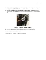
Connect the other end of the cable to the accessory receptacle on the compressor.
4.
Reconnect the compressor to its power source.
The system can now be operated from the compressor or from customer’s remote switch.
When using the customer’s remote on/off switch, the power switch on the compressor must
be in the stop (off) position.
5.
To verify that the cable installation is correct, close customer’s remote switch. Run the
system for one minute, then stop.
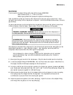
NOTE
When customer’s remote switch starts the compressor, it cannot be stopped
by
the
compressor’s power switch. Open the compressor’s circuit breaker to stop it
locally. When the compressor is started at the compressor power switch, it
cannot be stopped at the remote on/off switch.
Prestart Check
1.
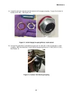
Check that the cooling water lines are connected and that the supply is connected to the
water in connection. Turn on the coolant and check the lines for leaks. Tighten the fittings if
necessary. See Cooling Requirements in Specifications.
2.
Check that all electric connections are made:
a.
Power to the compressor
b.
Cold head cable
3.
Check that the mains circuit breaker switch is open (handle is down) and the electrical
power supply is switched ON.
4.
Check that the equalization pressure is as specified when the compressor is at room
temperature, 20° C (68° F). A change in temperature, higher or lower, will cause a small
change, higher or lower, in the equalization pressure. If the pressure is far from the
specified equalization pressure, the gas charge is incorrect and may indicate a leak or
incorrect filling.
Содержание F-20L
Страница 2: ......
Страница 10: ...6 This page is intentionally blank...
Страница 12: ...8 This page is intentionally blank...
Страница 23: ...Specifications 19 Figure 2 F 20L Compressor Front View...
Страница 24: ...Specifications 20 Figure 3 F 20L Compressor Dimensions Dimensions are in inches and mm...
Страница 34: ...30 This page is intentionally blank...
Страница 36: ...32 This page is intentionally blank...
Страница 48: ...44 This page is intentionally blank...
Страница 53: ...Troubleshooting 49 Figure 19 F 20L Compressor Wiring Diagram...
Страница 54: ...Troubleshooting 50 Figure 20 F 20L Compressor Wiring Schematic...