


Installation
28
4.
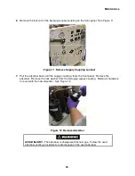
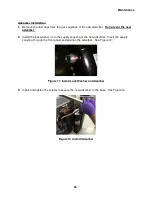
Connect the gas lines to the compressor’s high-pressure (supply) and low-pressure (return)
couplings. Use two wrenches to tighten the coupling. Torque all couplings to 47 ± 7 Nm (35
± 5 ft. lbs.) See Figure 7. Tighten each coupling before proceeding to the next one.
AVOID GAS LEAKS.
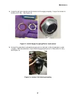
Check the condition of the gasket seal on the male half of
each Aeroquip coupling. Be sure the gasket seal is in place and the sealing
surfaces on both the male and female halves are clean before connecting.
Replace the gasket seal if it is damaged or missing.
Keep the gas line couplings aligned when making or breaking a coupling
connection. Leaks can occur due to the weight of the gas line or due to a sharp
bend near the connection.
NOTE
Retain the dust caps and plugs to re-cover the couplings when they are not in
use. They protect the couplings from damage and prevent the entry of
contaminants.
Figure 7 Connect Gas Line to Compressor or Cold Head
5.
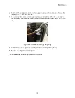
Using two wrenches, connect the RETURN gas line to the RETURN coupling on the cold
head. Tighten the coupling to 47 ± 7 Nm (35 ± 5 ft. lbs.).
6.
Using two wrenches, connect the SUPPLY gas line to the SUPPLY coupling on the cold
head. Tighten the coupling to 47 ± 7 Nm (35 ± 5 ft. lbs.).
The system equalization pressure, shown by the compressor gauge after all components have
been connected, will determine if charging or venting is required. System equalization pressure
should equal the value provided in the system level manual or the Specification section of this
manual.
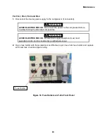
Install the Cold Head Cable(s)
1.
Ensure the compressor’s circuit breaker is in the OFF position (handle down).
2.
Connect the applicable cold head cable to the cold head receptacle on a compressor front
panel.
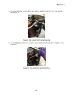
3.
Connect the other end of the cold head cable to the electrical receptacle on the cold head.
Содержание F-20L
Страница 2: ......
Страница 10: ...6 This page is intentionally blank...
Страница 12: ...8 This page is intentionally blank...
Страница 23: ...Specifications 19 Figure 2 F 20L Compressor Front View...
Страница 24: ...Specifications 20 Figure 3 F 20L Compressor Dimensions Dimensions are in inches and mm...
Страница 34: ...30 This page is intentionally blank...
Страница 36: ...32 This page is intentionally blank...
Страница 48: ...44 This page is intentionally blank...
Страница 53: ...Troubleshooting 49 Figure 19 F 20L Compressor Wiring Diagram...
Страница 54: ...Troubleshooting 50 Figure 20 F 20L Compressor Wiring Schematic...