


ES-8 MOBILE APPLICATION MANUAL R00
SECTION 4
16
FLUID MANAGEMENT SYSTEM
The Fluid Management System consists of a multi--
chambered primary/secondary separator, the final
air/fluid separator element, cooler bypass and fluid
filter.
As compressed air/fluid enters the sump, the first
fluid separation takes place due to a reduction of flow
speed coupled with a change of direction of the flow
within the sump housing. The compressed air
reaches the separator and the finest fluid drops and
mist are separated.
The minimum pressure/discharge check valve is
mounted on the compressor drive housing. Its
functions are as follows:
1. Maintains a minimum sump pressure of 60
psig (4.2 bar) under full load operation to
help assure adequate fluid pressure.
2. Acts as a check valve to isolate the compres-
sor from the system at shutdown or unload.
DRIVE MOTOR
The Drive Motor consists of a squirrel cage induction
motor which is connected to the integrated drive
gearing by a drive coupling.
4.4
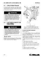
COMPRESSOR COOLING
SYSTEM, FUNCTIONAL
DESCRIPTION
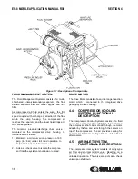
The Compressor Cooling System consists of a fluid
cooler, fan and cooler shroud. The fan is mounted on
the compressor shaft. Air is drawn through the motor
adaptor by the fan and exits through the coolers on
top of the compressor. The air provides cooling for
compressor fluid and cooling of air on units with air
aftercoolers.
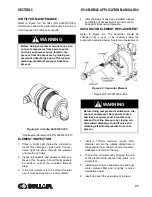
4.5
AIR INLET SYSTEM,
FUNCTIONAL DESCRIPTION
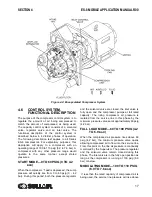
The compressor inlet system consists of a dry-type
air filter and an inlet control valve. Reacting on a
pressure signal, the valve closes the intake for
unloaded operation. The valve also acts as a check
valve upon shutdown.
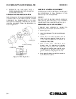
Figure 4-1: Description of Components
Содержание 30XH
Страница 10: ...NOTES 10 ...
Страница 22: ...NOTES 22 ...
Страница 33: ...NOTES 33 ...
Страница 34: ...INLET CONTROL SEAL DRIVE GEAR AND PARTS 34 8 3 INLET CONTROL SEAL DRIVE GEAR AND PARTS ...
Страница 36: ...MOTOR COUPLING FAN AND PARTS 36 8 4 MOTOR COUPLING FAN AND PARTS ...
Страница 40: ...COMPRESSOR COOLER SYSTEM AND PARTS 40 8 6 COMPRESSOR COOLER SYSTEM AND PARTS ...
Страница 42: ...PNEUMATIC CONTROL SYSTEM AND PARTS 42 8 7 PNEUMATIC CONTROL SYSTEM AND PARTS ...
Страница 44: ...CONTROL STARTER MFV 44 8 8 CONTROL STARTER MFV ...
Страница 46: ...DECAL GROUP 46 8 9 DECAL GROUP ...
Страница 48: ...DECAL GROUP 48 8 9 DECAL GROUP CONTINUED ...
Страница 50: ...WIRING DIAGRAM FULL VOLTAGE STANDARD 50 8 10 WIRING DIAGRAM FULL VOLTAGE STANDARD ...
Страница 51: ...NOTES 51 ...