68
EN/06.2018/G42 © STULZ GmbH – all rights reserved
cybercool 2 scroll original insTrUcTions
Compressor
In the compressor there is an ester oil charge, which does not have to be renewed under normal operation
conditions and holds out for the unit‘s lifetime. However, it is possible that the ester oil, as it reacts hygroscop
-
ically, has taken up humidity of the air after repeated recharging of the refrigerant circuit due to repair works.
The interaction between ester oil and water results in the formation of acid. Owing to a hyperacidity, corrosive
processes take place inside the compressor.
• In this case exchange the ester oil.
Oil level
During unit idleness the oil level should not be below the lower quarter (bottom line) and not rise above the
upper line during operation.
Oil type:
ICI Emkarate RL 32-3MAF (factory filling)
ICI Emkarate RL 32 CF
• Check the oil level by looking at the sight glass in the oil compensation line (for size 3/4 directly on the
compressor).
Crankcase heater
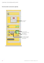
Check the crankcase heater function by measuring the ohmic resistance at the terminals of the auxiliary con
-
tactor in the electric cabinet. For the 140W heater the ohmic resistance should approximately be 1,1 kOhm,
1,3 kOhm for the 120W heater and 1,8 kOhm for the 90W heater.
Expansion valve
The refrigerant circuit is equipped with an electronic expansion valve, which controls the superheating in the
evaporator. The superheating is adjusted to 5 K at the factory and may not be modified.
• Check the superheating setpoint.
• Check the superheating by the command "eev 1" in the first refrigerant circuit resp. "eev 2" in the second
refrigerant circuit. If the superheating is below 3 K or above 7 K for a longer time, the function of the expan
-
sion valve is faulty.
• Check whether the refrigerant, pressure sensor and valve type are correctly set in the C7000.
The following valve type "Carel EXV" (valve type: 1) must be set. The following pressure sensor "0...17,3
barg" (Sensortype evaporating pressure: 4) must be set.
• Switch off all components of the refrigerant circuit and control the expansion valve in manual mode.
• Through control of the sight glass on the valve, check the mechanical operation of the valve.
• Compare the suction pressure measured by the valve sensor with the value of the suction pressure gauge in
the compressor section. Compare the suction gas temperature measured by the valve sensor, with the value
of a reference sensor at the suction line.
If you can find no deviation at all checks, probably the control module of the valve is defective and must be
replaced.
The expansion valve can freeze, if the humidity in the refrigerant circuit is excessive.
dAngER
do not thaw by soldering flame, danger of explosion !
Thaw with moist warm cloth. Check the sight glass.
Содержание CQO 1102 ASF
Страница 4: ...4 4 EN 06 2018 G42 STULZ GmbH all rights reserved CYBERCOOL 2 SCROLL ORIGINAL INSTRUCTIONS...
Страница 85: ......


