64
EN/06.2018/G42 © STULZ GmbH – all rights reserved
cybercool 2 scroll original insTrUcTions
• Connect pressure gauges on the high pressure and low pressure side and verify by reading the pressures,
that the saturation temperatures for evaporation (low pressure side) and condensation (high pressure side),
which correspond to the measured pressures, are within the following tolerances during the operation.
High pressure side: max. 18 K above the air intake temperature of the condenser
Low pressure side:
3 to 7 K beneath the chilled water flow temperature
Example:
measured on the high pressure side: 31 bar (rel.) (= 32 bar abs.)
corresponding saturation temperature at the dew point according to scale for R410A: 52,3°C
measured air intake temperature at the condenser: 35°C
t
cond
- t
air
= 52.3°C - 35°C = 17.3 K ---> ok
measured on the low pressure side: 8.3 bar (rel.) (= 9.3 bar abs.)
corresponding saturation temperature at the dew point according to scale for R410A: 5.0°C
measured flow water temperature at the evaporator outlet: 12°C
t
flow
- t
evap.
= 12°C - 5,0°C = 7 K ---> ok
If the tolerances (18 K at the condenser, 7 K at the evaporator) are exceeded, there is a problem of heat trans-
mission. The probable cause is the pollution of the heat exchanger surfaces. Also the superheating may be set
too high.
For all units
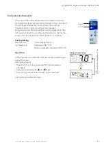
• Switch off the manual mode for all components.
• Instruct the operational staff of the controller manipulation (refer to the C7000 controller manual).
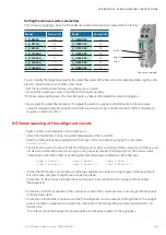
comp 2 hand 0
handoff
comp 1 hand 1
comp 1 handon 0
For units with two circuits only (Construction sizes 4 to 7)
• Now switch off the compressors of the first refrigerant circuit by manual mode.
• Check the correct function of the second refrigerant circuit by switching off the manual mode for
compressor 2 (possibly 4 and 6) and by producing a cooling capacity request (providing approx.
18°C warm water chilled water inlet of the chiller or by setting the water temperature setpoint suf-
ficiently low).
The compressors of the 2
nd
circuit will now be started by automatic operation of the C7000 controller.
• Perform the same checks as for the first refrigerant circuit.
comp 3 hand 1
comp 3 handon 0
comp 5 hand 1
comp 5 handon 0
comp 4 hand 0
comp 6 hand 0
Содержание CQO 1102 ASF
Страница 4: ...4 4 EN 06 2018 G42 STULZ GmbH all rights reserved CYBERCOOL 2 SCROLL ORIGINAL INSTRUCTIONS...
Страница 85: ......


