


Model 5402 User Guide
Issue 3, August 2021
Studio Technologies, Inc.
Page 31
Model 5402
DANTE LEADER CLOCK WITH GNSS SYNCHRONIZATION
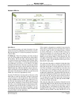
Menu Text and Links
The following provides details on some of the text and links
that are presented on the Model 5402’s webpages.
Device Name:
In the upper-right corner of each Model
5402 webpage is the Dante device name. This name is
unique to each device in a Dante deployment and is used
as part of the Dante subscription (channel routing) process.
The name can be changed from within the Dante Controller
application.
Identify Device Link:
In the upper-right corner of each
webpage, directly below the device name, is a link called
Identify Device. Clicking on it will cause the Dante identify
action to commence on the specific Model 5402. The action
will consist of the front-panel display’s green backlight flash-
ing five times. This command will help confirm that the web
server on the desired Model 5402 is being accessed.
Company Name Link:
On the bottom of each webpage
is a link with the title Studio Technologies, Inc. Clicking on
this link will cause the browser to open the Home webpage
of the Studio Technologies website.
Log Out Link:
In the upper-right corner of most of the
Configuration menu webpages is a link called Log Out. It
will cause the Model 5402’s web server to end the session,
logging out the user and returning to the Home menu. To
again access the configuration webpages requires that the
user click on the Login tab and provide a valid user name
and password.
Operation
Now that the Model 5402 is installed and configured it’s
ready for use. The unit is designed for continuous, unat-
tended operation. However, there are a number of nuances
in the unit’s operation. This may make it worthwhile for
personnel to spend some time reviewing this section.
Upon application of AC mains or DC power, the Model 5402
will go through a power-up sequence. The nine bi-color
LEDs on the Model 5402’s front panel will light green, then
light red in a confirmation sequence. The unit’s graphics
display will show the Studio Technologies logo graphics
image, followed by a menu page that shows the product
name (Model 5402) and the Dante name. Then the version
number of the Main MCU firmware will display. After a few
seconds the screen saver mode, detailed later in this sec-
tion, will begin operation.
Upon power being applied the green LED adjacent to the
USB receptacle on the back panel will flash once to indicate
that its associated circuitry is performing correctly. Also,
upon power being applied to the Model 5402 the LEDs on
the back panel associated with the unit’s three Ethernet
RJ45 jacks will briefly flash as a functional test.
After the Model 5402 has completed its power-up se-
quences the unit will begin operation. The nine front-panel
LEDs will reflect the real-time status of the unit’s major
functions. The front-panel display will allow the viewing
of over 25 menu pages showing status and configuration
conditions. In addition, using the front-panel pushbutton
switches some of the unit’s configuration settings can be
revised as required.
The following paragraphs will detail the operation of the
front-panel LEDs.
Power LEDs
Two LEDs indicate the presence of incoming AC mains
and nominal 12 volts DC power. They are labeled AC and
DC and can light green or red. When a source of AC mains
power is connected the AC LED will light green. (This is
actually in response to 12 volts DC that is being gener-
ated by the internally located AC mains input/12 volts DC
output power supply.) The LED labeled DC will light green
whenever a connected DC source exceeds approximately
10 volts. The DC LED will light red when the DC input is
between approximately 9 and 10 volts, indicating a low-volt-
age condition. Once the DC input is less than approximately
9 volts the DC LED will not light and the Model 5402 will
no longer operate from the DC source.
Network LEDs
Three LEDs provide status indications related to the Model
5402’s three Ethernet network interfaces. Two of the LEDs
are associated with the Model 5402’s Dante primary and
Dante secondary Ethernet ports. They are labeled PRI
and SEC. The third LED, labeled MGMT, is associated
with the unit’s management Ethernet port. The way in
which the three Ethernet interfaces and their associated
status LEDs function depend on the network configuration
as selected using the Dante Controller application. The
choices are Switched, Redundant, SMgmt, and
ReMgmt.
Switched Network Operation
PRI LED: The PRI LED will light red when no Ethernet
connection is present on the Dante primary or Dante
secondary Ethernet ports. It will light green whenever a
Gigabit Ethernet connection is present on either the Dante
primary or the Dante secondary Ethernet port and a link
has been established. It will light orange whenever a 100
Mb/s Ethernet connection is present on either the Dante
primary or the Dante secondary Ethernet port and a link
has been established.
SEC LED: The SEC LED will not light.
MGMT LED: When no Ethernet connection is present on
the management Ethernet port the MGMT LED will not light.
Содержание Dante 5402
Страница 2: ...This page intentionally left blank...