


Model 5402 User Guide
Issue 3, August 2021
Studio Technologies, Inc.
Page 11
Model 5402
DANTE LEADER CLOCK WITH GNSS SYNCHRONIZATION
Units intended for use in other destinations require that an
appropriate mains cord be obtained. The wire colors in the
mains cord should conform to the internationally recognized
color code and be terminated accordingly:
Connection
Wire Color
Neutral (N)
Light Blue
Line (L)
Brown
Earth/Ground (E)
Green/Yellow
Because the Model 5402 does not contain a power on/off
switch it will begin operation as soon as AC mains power
is connected.
Safety Warning: The Model 5402 does not contain an
AC mains disconnect switch. As such, the AC mains
cord plug serves as the disconnection device. Safety
considerations require that the plug and associated
inlet be easily accessible to allow rapid disconnection
of AC mains power should it prove necessary.
Connecting DC Power
The Model 5402 can also operate from a source of 10 to 18
volts DC. The current required from a 12 volts DC source
is 0.5 ampere (500 milliamperes) maximum. A 4-pin male
XLR connector, located on the unit’s back panel, is used
to connect the source of DC. Prepare a mating connector
(female) so that pin 1 is DC– and pin 4 is DC+. Pins 2
and 3 are not used and should remain unconnected. This
connector type and pinout have become a broadcast DC
power standard and should be familiar to many technical
personnel. Because the Model 5402 contains no power
on/off switch it will begin operation as soon as a DC power
source is connected.
As previously mentioned, both an AC mains source and a
DC source can be connected at the same time. If this is
the implementation then the AC mains source will always
power the Model 5402 with the DC source serving as a “hot
standby.” Only if the AC source fails will the unit draw power
from the DC source. This will occur automatically with no
interruption of Model 5402 operation. In this “standby”
mode (when an AC mains source is connected) the Model
5402 draws less than 110 microamperes (uA) from a 12
volts DC input.
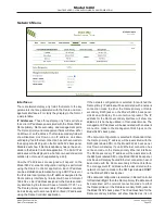
Dante Configuration
For audio and timing to correctly pass from the Model 5402
requires that several Dante-related parameters be config-
ured. These configuration settings are stored in non-volatile
memory within the Model 5402’s Dante network interface
circuitry. Configuration will typically be done with the Dante
Controller software application, available for download free
of charge at audinate.com. Refer to Appendix C of the list
of the Model 5402’s Dante Controller default configura-
tion. Versions of Dante Controller are available to support
several operating systems.
The Model 5402’s Dante interface is compatible with the
Dante Domain Manager (DDM) software application. Refer
to DDM documentation, also available from Audinate, for
details on which Model 5402 and related parameters may
have to be configured.
Audio Routing
The Model 5402’s eight Dante transmitter (output) chan-
nels can be assigned to the desired Dante receiver (input)
channels on associated equipment. This will route the
eight channels associated with the tone generator func-
tion. Within Dante Controller a “subscription” is the term
used for routing a transmitter flow (a group of up to four
output channels) to a receiver flow (a group of up to four
input channels).
The Model 5402 uses a Brooklyn II module to implement its
Dante functionality. The number of transmitter flows associ-
ated with this module is 32 and, as such, typically no flow
limitation should occur. These flows can either be unicast,
multicast, or a combination of the two. Note, however, that
when AES67 mode is enabled in Dante Controller the Dante
transmitter (output) channels will only function in multicast;
unicast is not supported.
Unit and Channel Names
The Model 5402 has a default Dante device name of
ST-M5402-
along with a unique suffix. The suffix identi-
fies the specific Model 5402 that is being configured. The
suffix’s actual alpha and/or numeric characters relate to
the MAC address of the unit’s Brooklyn II module. The
eight Dante transmitter (output) channels associated with
the tone outputs have default names of
Tone 1
through
Tone 8
. Using Dante Controller, the device and chan-
nel names can be revised as appropriate for a specific
application.
Device Configuration
The Model 5402 supports audio sample rates of 44.1, 48,
88.2, 96, 176.4, and 192 kHz with no pull-up/down options
available. The digital audio data is in the form of 24-bit
pulse-code modulation (PCM 24) samples. Clocking- and
latency-related parameters can be adjusted if required
in Dante Controller but the default values are typically
correct.
Network Configuration – Dante
As has been covered previously in this guide, the Model
5402 allows connection of one, two, or three Ethernet
signals using standard RJ45 jacks which are located on
the back panel. In many applications two of the jacks will
Содержание Dante 5402
Страница 2: ...This page intentionally left blank...


