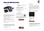
a. Connect the Ethernet
cable between the
Ethernet gateway and
the router
b. Connect the serial cable
between the Ethernet
gateway and the
Xcom-232i
c. Connect the power
supply cable between the
Ethernet gateway and
the Xcom-232i
d. Connect the communi-
cation cable between
the Xcom-232i and the
Xtender system
Contents of the Xcom-LAN
remote communication set
Micro SD
card
with adapter
Router
How to configure and to install the Xcom-LAN
Insert the Micro SD card
into the computer
Additional items needed
Communication cable,
2m
2x 2 DIN rail clips
and screws
7.
1.
2.
Mounting plate for
the Xcom-232i
Computer or
mobile phone
15:45
Xcom-232i
Ethernet gateway
Serial cable, 0.25m
Ethernet cable, 3m
Mount the different products
within the Studer system
3.
The products should be mounted on a
smooth surface.
The distance between the Xcom-232i and
the Studer system should
not exceed 10
meters
.
The distance between the Xcom-232i and
the Ethernet gateway should not exceed
0.25 m.
All cables you need are provided in the set.
ATTENTION!
The metallic casing of the Ethernet gateway
is connected to the negative battery pole.
Therefore it is necessary to
isolate its casing
from any metallic surface.
Wiring
Set the terminations
4.
5.
It is very important to set the terminations correctly for the functionning of the system.
With one device in the system the termination on the Studer device should be put to T as in "Termi
-
nated". With more than one device in the system all Studer devices should be put to O as in "Open"
apart from the devices at the end of the communication chain. These devices should be put to T
as in "Terminated".
The termination switch next to the two RJ45 connectors on the Xcom-232i must be set in position T.
Turn on the power
6.
a
b
c
d
Power supply cable
RJ45-Jack, 0.5m
Internet access
Pads


