background image

Studer Innotec SA

BSP 


User manual 

V1.3 

11  

3.2


S

HUNT MOUNTING


The  shunt  supplied  with  the  device  allows  the  measurement  of  the  battery  current.  It  must 
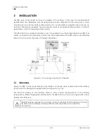
imperatively be installed in series with the negative terminal of the battery. The connection (a) of 
the  figure  3.1  must  be  as  short  as  possible.  For  a  good  operating  of  the  charge  estimating 
algorithm, all the current must go through the shunt. No other conductive component shall be 
connected to the negative terminal of the battery. 


3.3


C

ABLING


The cabling schematic is available on figure 3.1. The cabling procedure is as follows: 

1.


Connect the shunt to the negative terminal of the battery (a). (Tightening torque: 20 Nm 
for the BSP500, 45 Nm for the BSP1200).  

2.


Connect the black and yellow wires of the BSP cable to the screw of the shunt on battery side 
(b). 

3.


Connect the blue wire of the BSP to the second screw of the shunt (c). 

4.


Connect the red wire with a fuse to the positive terminal of the battery (d). 


It might happen while connecting the red wire to the battery that a spark is 
generated. No damage is likely to happen or to damage the device. 

5. Connect the negative cables of the inverter, the solar regulator and/or DC consumers to the 
free bolt of the shunt. The positive cables are being connected straight to the positive terminal 
of the battery (e). 

6. Connect the communication cable to the communication bus of the Xtender system and 
activate, if necessary, the link end (f). For more information, see the section 3.4. 

3.4


C

ONNECTING THE COMMUNICATION BUS


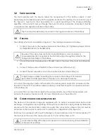
The  devices  of  the  Xtender  range  are  equipped  with  an  owned  communication  bus  for  data 
exchange, configuration and updating of the system. Connection is being made by linking the 
devices with the communication cables. One gets then a bus online where a link end must be 
activated on the devices on each end, to obtain the configuration of the figure 3.2 

Each device is equipped with a switch offering to choose between open "O" and terminated "T". 
The devices at the end of the line must be set on "T" and all the others on "O". 


An incorrect setting of the link ends can lead to an erratic running of the installation 
or impede its updating. 


The shunt must be exclusively mounted on the negative terminal of the battery. 


Beware of the cable cross section! All current (X solar module(s) or 
consumer(s) directly connected to the DC side) will go through this cable for the 
charge and discharge of the battery. 

Содержание BSP

Страница 1: ...Studer Innotec SA 2017 V1 3 4O9H Battery Status Processor BSP User Manual ...

Страница 2: ...www studer innotec com en downloads LEGAL NOTICE The use of Studer Innotec SA devices is the responsibility of the customer in all cases Studer Innotec SA reserves the right to make any modification to the product without prior notice PRODUCT RECYCLING The BSP conforms to the European directive 2011 65 EU on hazardous substances and does not contain the following elements lead cadmium mercury hexa...

Страница 3: ...the communication bus 11 3 5 Signalisation LED 12 4 QUICK START GUIDE 13 4 1 Choosing the battery capacity 13 4 2 Choosing the shunt 13 4 3 Reset the battery history to zero 14 5 DISPLAY OF THE STATE OF THE BATTERY 14 5 1 Graph of the state of charge history 14 5 2 Values to display 14 6 SETTING OF THE PARAMETERS 16 6 1 Generalities 16 6 2 Levels of use and of accessibility 16 6 3 Basic settings 6...

Страница 4: ...rcuit voltage 6044 18 6 4 10 Battery current limitation activated 6058 18 6 4 11 Max battery charge current 6059 18 6 4 12 Self discharge rate 6019 18 6 4 13 Nominal temperature 6020 19 6 4 14 Temperature coefficient 6021 19 6 4 15 Charge efficiency factor 6022 19 6 4 16 Peukert s exponent 6023 19 6 4 17 Use C20 capacity as reference value 6049 19 6 5 Configuration as simple counter 19 7 FACTORY S...

Страница 5: ...instance that of a petrol gauge The different values that affect a battery are described below 1 1 1 Definition of battery capacity A battery s capacity is defined as the amount of electrical charge that a full battery can supply at given current before reaching a certain voltage Normally the unit Ampere hour Ah is used for its measurement An ideal 100 Ah battery should for instance supply 10 Ampe...

Страница 6: ...y 1 25 Cref and Iref refer to the given capacity at a known current Discharge speed Capacity at C10 100 Ah at 10 A during 10 hours C3 0 74 C20 1 19 C50 1 50 C100 1 78 Capacity ratio with a Peukert exponent of 1 25 1 1 5 Capacity and battery lifetime The capacity decreases along the charge discharge cycles The deep discharges have a particularly negative impact High ambient temperatures lower also ...

Страница 7: ... SA Nuts or screws partially or insufficiently tight during installation or maintenance Damages due to atmospheric overvoltage lightning Damages due to transport or improper packaging Disappearing of original marking items 1 3 2 Disclaimer of liability Installation commissioning use and maintenance of this device cannot be supervised by the company Studer Innotec SA For this reason we do not accep...

Страница 8: ...to do any change modification or repair whatsoever Regarding authorized modifications and replacements only genuine components shall be used This device is meant for a use only indoor and must under no circumstances stand in the rain the snow or any other humid or dusty environment In case of use in motor vehicles this device must also be protected against vibrations by absorbing components 1 4 3 ...

Страница 9: ... the following EC directives and norms Low voltage directive LVD 2014 35 EU EN 62368 1 2014 Electromagnetic Compliance EMC Directive 2014 30 EU EN 61000 6 2 2005 EN 61000 6 4 2007 A1 2011 Studer Innotec SA contact details Studer Innotec SA Rue des Casernes 57 CH 1950 Sion Switzerland 41 0 27 205 60 80 41 0 27 205 60 88 info studer innotec com www studer innotec com ...

Страница 10: ... sensor BTS that will be connected to the Xtender In that case the temperature of the BTS will be automatically taken into account for the state of charge calculation Figure 3 1 Connecting schematic of the BSP 3 1 MOUNTING Ideally the BSP can be stuck directly to the battery It can also be mounted close to the battery by means of the fixing plate supplied with see figure 3 2 p 12 The direct mounti...

Страница 11: ...ect the negative cables of the inverter the solar regulator and or DC consumers to the free bolt of the shunt The positive cables are being connected straight to the positive terminal of the battery e 6 Connect the communication cable to the communication bus of the Xtender system and activate if necessary the link end f For more information see the section 3 4 3 4 CONNECTING THE COMMUNICATION BUS...

Страница 12: ...r When the BSP is connected with the communication bus to other devices Xtender VarioTrack RCC Xcom or other the software versions may not be compatible It is highly recommended to make a software update of all components in the system in order to guarantee all functionalities Therefore before starting the setup of the device download the latest software version from our website www studer innotec...

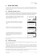
Страница 13: ... DOWN to the general menu Then push on SET to enter the menu With the arrow DOWN move to the parameter Battery Capacity To modify its value push on SET The value turns in reverse video Change the value for the one of your battery with the keys UP and DOWN Confirm by pushing on SET Then configure the parameter Nominal Discharge Time C rating 6002 the same way as for the battery capacity 4 2 CHOOSIN...

Страница 14: ... selection mode with the key SET The battery is then selected The key SET allows then to display the graph The graph of the state of charge is then displayed On the horizontal scale are today and the last 4 days The graduations indicate every hour from midnight to midnight Each horizontal pixel means one hour The vertical axis gives the state of charge of the battery The graduations mean 20 40 60 ...

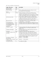
Страница 15: ...he BTS is connected or if not present Ah charged today Ah Charge supplied to the battery from midnight until now Ah discharged today Ah Charge supplied by the battery from midnight until now Ah charged yesterday Ah Ah discharged yesterday Ah Total kAh charged kAh Charge supplied to the battery from the last reset to zero of the battery history See Reset of battery history 6003 p 17 Total kAh disch...

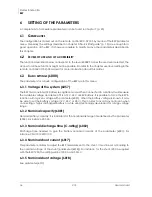
Страница 16: ...an automatic battery recognition mode When connected to a battery it will measure the available voltage and detect if it is a 12 V 24 V or 48V battery It is possible to force the BSP to function with a given voltage with parameter 6057 When the battery voltage is known it may be wise to set the battery voltage 12 V 24 V or 48 V This in order to avoid any confusion when connecting a highly discharg...

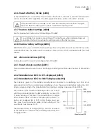
Страница 17: ...nstaller 6 4 ADVANCED SETTINGS 6016 Parameters used for advanced configuration of the BSP 6 4 1 Reset of user counters 6031 This parameter allows to reset to zero the charge discharge and time user counters of the section 5 2 6 4 2 Manufacturer SOC for 0 displayed 6055 6 4 3 Manufacturer SOC for 100 displayed 6056 The capacity given by the battery manufacturer conforms to a discharge test that is ...

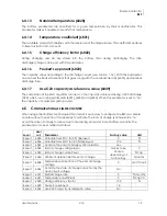
Страница 18: ...th parameter 6024 can be corrected with this coefficient By using a reference temperature of 25 C it is possible to have a similar charge behaviour of the Xtender the VarioTrack or the VarioString 6 4 9 Activate the state of charge correction by the open circuit voltage 6044 When this parameter is activated the state of charge is corrected by the battery voltage This function is only effective for...

Страница 19: ...n this parameter is set to no the capacity of parameter 6001 is used 6 5 CONFIGURATION AS SIMPLE COUNTER When using other battery technologies than lead it is necessary to configure the BSP as a simple counter without correction It is necessary to activate the end of charge synchronisation to avoid the state of charge to derive due to measuring errors and loss of battery capacity The parameters ca...

Страница 20: ...ge level 13 2 26 4 52 8 V Expert 6025 End of charge current level 2 cap Expert 6065 Minimum duration before end of charge 5 minutes Expert 6031 Reset of user counters Expert 6042 Activate the end of charge synchronization No Expert 6044 Activate the state of charge correction by the open circuit voltage Yes Expert 6048 Temperature correction of the end of charge voltage 0 mV C cell Expert 6049 Use...

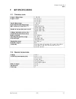
Страница 21: ...A BSP 1200 Voltage measurement accuracy 0 3 Current measurement accuracy 0 5 Battery capacity 20 20000 Ah Operating temperature range 20 55 C Packed weight 900 g BSP 500 1500 g BSP 1200 Displayable values see table 6 1 Protection degree IP20 Conformity LVD 2014 35 EU EN 62368 1 2014 EMC 2014 30 EU EN 61000 6 2 2005 EN 61000 6 4 2007 A1 2011 RoHS 2011 65 EU 9 2 READOUT RESOLUTIONS Voltage 0 01 V Cu...

Страница 22: ...Studer Innotec SA BSP 22 V1 3 User manual 9 3 DIMENSIONS ...

Страница 23: ...Studer Innotec SA BSP User manual V1 3 23 9 4 MOUNTING ...

Страница 24: ...Studer Innotec SA Rue des Casernes 57 CH 1950 Sion Switzerland 41 0 27 205 60 80 41 0 27 205 60 88 info studer innotec com www studer innotec com ...

Отзывы: