STREBEL CIS
ASSEMBLY INSTRUCTIONS FOR:
STREBEL CIS
Page 11
V.1-03.08
Assembly of fixtures
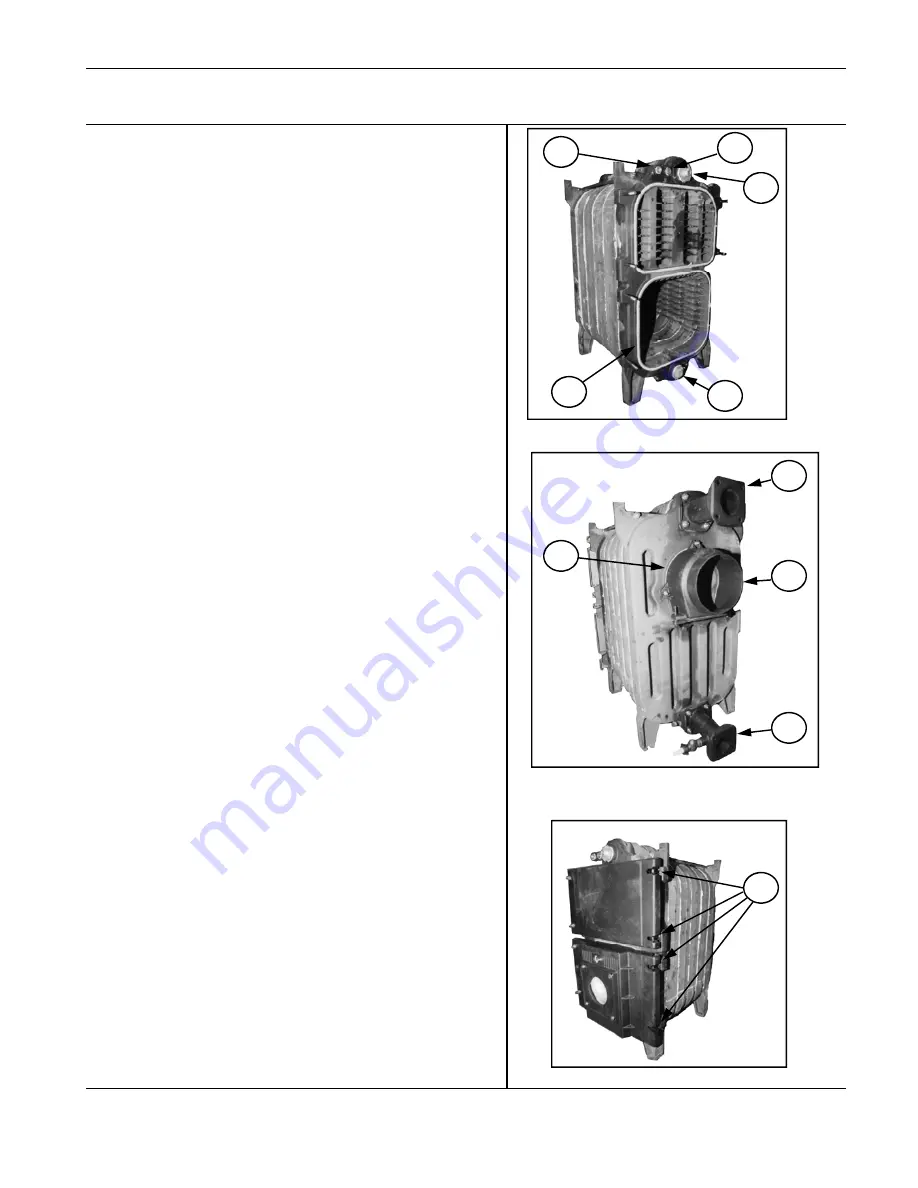
1. Fit 2” plug into the bottom tapping on the front section of the boiler (A).
2. Fit the 2” x 1/2” bush to the upper tapping of the boiler front section for the
thermostat pocket (B+C).
3. Next fit the thermostat pocket (1/2” diameter) into the bush (B).
4. Fit the thermometer pocket into the tapping immediately to the right of the self
closing valve (C)
5. Fit the 1/2” self-closing valve for the altitude (pressure) gauge into the upper
left hand tapping (D)
6. Fit the injector into the return connection with joggle to the bottom.
7. Connect flange to the lower return connection.
8. Connect the flow header to the upper tapping of the rear section.
Burner door assembly
1. Attach M12 screw with eye into the tapping on the front section ensuring that
there is a 40mm gap between the centre of the eyelet to the edge of the front
section and tighten locking nut (J).
2. Attach the threaded bolts M12 x 80 mm into the right hand tappings on the
lower half of the front section.
3. Put ceramic sealing cord into the groove on the lower part of the front section
(I).
4. Place burner door with insulation onto the eyelets and insert hinge pins 12 x
63 mm.
5. Close burner door, check alignment and tighten nuts M12 with washers.
6. Attach burner flange plate onto burner door.
7. Repeat procedure swapping eye bolt fixings with threaded bolts fitting the
hinge on the right hand side, if required.
Upper flue-way door
Use the same procedure as above to fit the flue-way door.
Boiler jacket assembly
1. Hang the insulated side jackets on the upwardly protruding jacket supports on
the front and rear sections.
2. Fit the rear bottom jacket to the side jackets by pushing the spring clips into
the side jackets and securing further up with M6 self tapping screws.
3. Repeat procedure with the rear upper jacket.
4. Fit the upper jacket and insulation by sliding over the side jackets and
securing with M6 self-tapping screws.
5. The lower front jacket is fitted by pushing together using spring clips.
Assembly of Flue Hood
1. Put the ceramic fibre sealing cord (900mm) into the groove in the rear section
of the boiler (G).
2. Align the complete flue hood casting and bolt on using the M8 nuts (H).
Flow and return connections
1. These are bolted onto the rear section of the boiler using the M12 nuts and
washers (E+F).
J
A
I
B
D
C
F
H
E
G


