background image

                                             Dimension BST 1200 / SST 1200 User Guide

  Setup  19

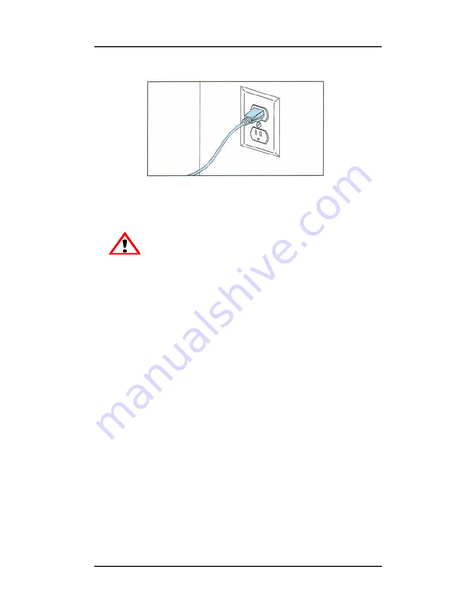
Figure 5: Connecting to a grounded electrical outlet

2.

Connect the female end of the power cord directly into the rear 
of the cabinet.

3.

Switch the Dimension


circuit breaker to the on (up) position.

The Dimension system is now ready to have power applied.

CAUTION

Do not use an extension cord or power 
strip with the Dimension system. Connect 
the cord directly into the receptacle or 
UPS. 

Содержание Dimension BST 1200

Страница 1: ...BST 1200 SST 1200 User Guide...

Страница 2: ...radio communications Operation of this equipment in a residential area is likely to cause harmful interference in which case the user will be required to correct the interference at his own expense Ch...

Страница 3: ...ling quickly The system models with ABS plastic so modeled parts are strong and durable ABS also ensures you ll be able to drill tap sand and paint your creations With the speed and convenience of Bre...

Страница 4: ...es not indicate a procedure that can cause injury or damage if it is not followed A NOTE will follow the paragraph of instruction to which it relates The Dimension printer guides you through operation...

Страница 5: ...ing Parts Removing Completed Parts and Removing Support Material The tasks presented are common procedures accomplished during the normal operation of the printer Maintenance Lists several tasks that...

Страница 6: ...6 DimensionBST1200 SST1200UserGuide...

Страница 7: ...sion 13 Supplies 14 Setup 15 Workspace 15 Unpacking 16 Installing Forklift Access Covers 18 Power Connections 18 Powering On Dimension 20 Insert Modeling Base 21 Installing Software 22 Networking Your...

Страница 8: ...ed Part 41 Removing Support Material 42 Breakaway Supports 42 Soluble Supports 43 Maintenance 45 Startup Kit Tools 45 After Each Build 46 Empty Purge Container 46 500 Hour Maintenance 46 Clean Fan Fil...

Страница 9: ...mension BST 1200 SST 1200 User Guide Troubleshooting 59 Troubleshooting Checklist 59 Fault Determination Codes 61 Loss of Extrusion 61 Diagnosing Loss of Extrusion 61 Recovering From Loss of Extrusion...

Страница 10: ...10 DimensionBST1200 SST1200UserGuide...

Страница 11: ...completion With two layer resolution settings you can choose to build a part quickly for design verification or you can choose a finer setting for higher quality surface detail Figure 1 Dimension Fro...

Страница 12: ...BST1200 SST1200UserGuide Figure 2 Dimension Rear View Item Nomenclature Item Nomenclature 1 Fan Cover 4 UPS Connection 2 Main Circuit Breaker 5 Diagnostic Hookup 3 Power Cord Adapter 6 Network Cable C...

Страница 13: ...nough to build continuously for about four days without reloading Finding More Information Several references are available for use with Dimension Setting up Dimension Dimension User Guide Step by ste...

Страница 14: ...0 Green ABS Filament Cartridge 340 20600 Yellow ABS Filament Cartridge 340 20800 Steel Gray ABS Filament Cartridge Breakaway Support Material BST Only 340 30000 Breakaway Support Cartridge Soluble Sup...

Страница 15: ...lbs System Dimensions 838 x 737 x 1143 mm 33 x 29 x 45 in Four inch minimum space behind unit for air circulation Dedicated outlet requirements 110 120 VAC 60 Hz 15 A min 20 amp recommended or 220 240...

Страница 16: ...nd remove the cardboard side panels 5 Remove the top foam 6 Remove outer plastic wrap use care if using a knife so as to not scratch the printer 7 Remove the foam door channels 2 and tape WARNING The...

Страница 17: ...printer and report any shipping damage to the carrier CAUTION Remove the foam tubes that isolate the extrusion head from the frame see Figure 3 The printer will be damaged if powered on with the foam...

Страница 18: ...tions for the printer Dimension is provided with two power cords one for 110 V and one for 220 V Prepare all power connections 1 Connect the male end of the supplied power cord directly into a grounde...

Страница 19: ...female end of the power cord directly into the rear of the cabinet 3 Switch the Dimension circuit breaker to the on up position The Dimension system is now ready to have power applied CAUTION Do not u...

Страница 20: ...NG Dimension s build chamber and extrusion head tip get very hot The chamber and head tip reach temperatures of approximately 75 C 167 F and 300 C 572 F respectively Personal injury can occur if prope...

Страница 21: ...mode Insert Modeling Base Make sure retainers are turned down so as not to interfere with the modeling base installation Set the modeling base on the Z Platform aligning the tabs on the modeling base...

Страница 22: ...on on page 22 A controller software CD is included in your Startup Kit Install CatalystEX 1 Insert the CatalystEX installation disc into your CD ROM drive The installation menu automatically appears 2...

Страница 23: ...possibly record the IP address in the CatalystEX program Establishing communication on a Dynamic network If you are on a Dynamic network or not sure of your network type follow these steps to allow t...

Страница 24: ...Network addresses 1 Obtain your network addresses from your Network Administrator 2 From Idle or Ready to Build press Maintenance The panel displays System Maintenance and the software version 3 Press...

Страница 25: ...OTE Detailed instructions for using CatalystEX can be found in the CatalystEX Help file A From the General Tab click the Manage 3D Printers button B Click the Add from Network button in the lower righ...

Страница 26: ...t a crossover cable from your printer directly into a network port on your PC A 14 foot crossover cable orange is included with the Start Up Kit 2 Make sure the printer is on and determine the Unique...

Страница 27: ...e appropriate fields C Enter the Dynamic IP Address for your printer from Step 2B in the appropriate field D Select the appropriate printer type from the drop down list E Click Add Printer and close t...

Страница 28: ...allowing your PC a minute or so to adjust to the new setting your PC should connect to your printer vii If you are still unable to connect to your printer recheck your connections and settings Contact...

Страница 29: ...of a larger multiple line LCD display on top and four single line context sensitive displays each with one button or key The top line in the large display always reveals the printer status The lower...

Страница 30: ...ng on a used modeling area may cause loss of extrusion or cause a part to curl or break loose from the modeling base NOTE Use CatalystEX Pack Tab to position a part on the modeling base Before inserti...

Страница 31: ...ff the system Cycling Power Situations may occur that require the removal of all power to the Dimension system followed by a restart This section discusses the procedure for this cycling of the electr...

Страница 32: ...life is more than one year if the cartridge package remains sealed Load material cartridges 1 Remove packaging 2 If present remove the red sealing plug from the cartridge see Figure 9 NOTE Plug must b...

Страница 33: ...With the cutter from your Startup Kit snip the filament flush with the end of the cartridge see Figure 11 on page 34 CAUTION Be careful when touching the pinch roller on the side of the cartridge If...

Страница 34: ...occurs if you do not insert the new cartridges within 30 seconds In this case the cartridge will not lock into its slot You must press the Retry button before continuing the process 9 The panel will...

Страница 35: ...hoose Figure 12 Close up of extrusion tips NOTE If the display shows Load Failed press Retry If load fails again remove the cartridge snip the material see Figure 11 on page 34 remove filament in the...

Страница 36: ...When unloading is complete the panel will prompt you to remove a cartridge based upon your choices i e Remove Both Cartridges Remove Model Top Cartridge or Remove Support Bottom Cartridge 2 Remove the...

Страница 37: ...send a test part to the printer Build a test part 1 Press Maintenance 2 Press Test Parts and select one of the available sample parts Dimension automatically starts building the part 3 When the part i...

Страница 38: ...iately send it to your Dimension for printing OR Click Pack to have CatalystEX process the part for printing but not send the part to your Dimension send the part to the printer later as part of a pac...

Страница 39: ...ead the display panel while building The top two lines of the display panel show printer status messages see Figure 14 The bottom line of the panel shows the material amounts remaining in the cartridg...

Страница 40: ...mes modeling Resuming Operations from Standby Mode After several minutes of inactivity Dimension enters Standby mode During Standby the head temperature will decrease to save energy Continue operation...

Страница 41: ...been opened and closed the panel asks Part Removed 4 Press Yes only after removing the part refer to Removing a Completed Part Removing a Completed Part When the part has completed the panel displays...

Страница 42: ...eling base front right to back left 2 Pull the part off the base or use a putty knife to pry the part completely off NOTE Supports are much easier to remove when the modeling base is still warm Removi...

Страница 43: ...pport material can be removed by hand with relative ease but is designed to be dissolved off of your parts for hands free part finishing Refer to the SST Process Guide for details regarding the remova...

Страница 44: ...44 Operation DimensionBST1200 SST1200UserGuide...

Страница 45: ...ent parts and a set of tools used to help you maintain the system The following is a list of the tools contained in the Startup Kit Needle Nose Pliers T Handled Wrench 1 8 inch T Handled Wrench 7 64 i...

Страница 46: ...container towards you and out of the chamber 3 Empty the container and reinstall on 3 mounts 500 Hour Maintenance NOTE For printer hours refer to the CatalystEX Printer Services tab Printer Info butto...

Страница 47: ...ides of cover Figure 15 Figure 15 Removing the Head Cover 4 Remove the old flicker loosen the flicker attachment rear screws and pull up on the flicker 5 Insert the new flicker and tighten the rear sc...

Страница 48: ...right making the Support Left Tip the active tip 12 Verify that the Support Tip Shroud touches the brush Raise the brush if necessary NOTE Ideally the top of the brush and the top of the flicker shou...

Страница 49: ...2 Y axis guide rods 2 and Z axis guide rods 2 See Figure 18 for locations Clean with isopropyl alcohol Lubricate using the Krytox grease provided in the Startup Kit Use the grease sparingly Figure 18...

Страница 50: ...er to remove all foreign particles and purged material Clean Door Glass The door glass can be cleaned with any commercial glass cleaner Chamber Light Bar Replace a chamber light bar when it burns out...

Страница 51: ...n tips Figure 19 Build up can be caused by an overflowing Purge Bucket or an improperly adjusted Tip Cleaning Assembly 1 Enter Head Maintenance tips must be hot to clean area A From Idle press Mainten...

Страница 52: ...ess Next The head will come to rest in the center of the chamber and the Z Platform will change position Choose Head Maintenance 2 Position the blade of the putty knife supplied with Start Up Kit betw...

Страница 53: ...to zero after replacement 1 Enter Tip Maintenance Replace Tips From Idle Select Maintenance then Next then Tip Maint then Replace The printer will display Load Model Unloading followed by Tip Maintena...

Страница 54: ...e the same as the MODEL tip shown in Figure 23 on page 55 The tips come in a Red capped container B For a Dimension SST you must identify the correct replacement tip The SST uses two tip types You mus...

Страница 55: ...Pull the tip shield toward you then lift up to install the tip F Push the tip toward the back of the printer once it is all the way up against the heater block G Verify the tip is fully inserted into...

Страница 56: ...d Model Replace Both Cartridges flashing If you want to replace a material cartridge do so now See Unloading Material paragraphs 2 and 3 on page 36 and Loading Material on page 32 If you do NOT want t...

Страница 57: ...minutes The printer will then automatically build an XY Calibration part approximately 10 minutes You must inspect the XY Calibration part and calibrate the X and Y axes for tip offset 1 When the XY C...

Страница 58: ...fset adjustment the value will change in the upper display window by default the printer will be ready to accept the X value E When you are satisfied with your X offset value Select Y and repeat the p...

Страница 59: ...ruding Filament may be jammed in extrusion head see Loss of Extrusion on page 61 Purge material accumulating on part Material may have accumulated behind tips See See Tip Area Clean up on page 51 Make...

Страница 60: ...in Catalyst and redownload to system Display Panel displays Can t Find Home Check Modeling Base Verify a modeling base is inserted Modeling base may be used or defective replace Display Panel displays...

Страница 61: ...peration If pressing Continue does not recover the printer the printer should be power cycled see Cycling Power on page 31 wait 60 seconds before switching power on again In most cases you will be abl...

Страница 62: ...p may not immediately extrude material After the tip reaches operating temperature you may need to wait up to 30 seconds before extrusion will begin 6 Press Stop to stop the extrusion 7 If material st...

Страница 63: ...ce mode From Idle press Maintenance then Next then Head Maintenance 2 Remove plastic head cover Remove plastic head cover by squeezing raised pads on sides of cover Figure 15 on page 47 3 Place the ti...

Страница 64: ...t tool B To facilitate access to areas that may need to be cleaned move the material idler wheels out of the way there is one idler wheel for support material and one for model material Figure 27 illu...

Страница 65: ...same side of the head assembly as the one on which you are working It is not necessary to keep Toggle Bar in a neutral position ii Insert 1 8 T handled hex driver from Start Up Kit into the fixturing...

Страница 66: ...ial in the other liquefier inlet area Clean the area as necessary 9 Install plastic head cover 10 Exit Maintenance press Next then Done 11 Unload the material Make sure that the cartridges are entirel...

Страница 67: ...Dimension BST 1200 SST 1200 User Guide Troubleshooting 67...

Страница 68: ...Troubleshooting DimensionBST1200 SST1200UserGuide 14950 Martin Drive Eden Prairie MN 55344 USA Telephone 952 937 3000 Fax 952 937 0070 Web Site www dimensionprinting com Stratasys Document 204398 000...

Отзывы: