background image

RA7000 and ESA10000 Storage Subsystems

2–24

EK–SMCPP–UG. A01

13.  For BA370’s with 4+4 power configurations, go to the rear of the cabinet

and plug the black ac power cord from the BA370’s ac power controller into
the bottom PDU that already has a black power cord plugged into it. For
dual-redundancy units, plug the gray ac power cord from the BA370’s ac
power controller into the top PDU in the rear of the SW600 cabinet. Attach
ECB cables to the ECB and to the cache modules  The top BA370 ECB is
located on the left-hand side of the ECB shelf. The bottom BA370 ECB is
located on the right-hand side of the ECB shelf.

14.  Plug the PDU ac power cable(s) into the ac power source.

2.4

Cabling a Master Enclosure to an Expansion Enclosure(s)

NOTE

One DS-BNK37-1E cable kit is required for each
expansion unit.

2.4.1  Cabling Sequence

When adding an expansion BA370 unit, the following sequence is suggested.

1.  Connect all six SE I/O cables between units..

2.  After the SE I/O cables are attached, connect the EMU communication

cable.

3.  The last step is to set the PVA address.

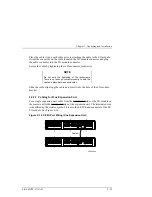
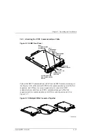
2.4.2  Attaching the SE I/O Cables

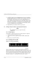
Figure 2–15  SE I/O Port Identification

CXO5819A

6

4

2

5

3

1

There is a separate cable for each port of the controller and all cables are
identical. Refer to Figure 2-15 and attach the cables to one port at a time. SE I/O
cables are connected port-to port maintaining the same port number at each end.
Port 1 of the master unit connects to port 1 of the expansion unit(s), port 2 of the
master unit connects to port 2 of the expansion unit(s), and so forth. Start with
the bottom row (ports 1, 3, 5) first then the top row (ports 2, 4, and 6).

Содержание ESA10000

Страница 1: ...RA7000 and ESA10000 Storage Subsystems User s Guide EK SMCPP UG A01 Digital Equipment Corporation Maynard Massachusetts...

Страница 2: ...nt Corporation or of any third party FCC Notice This equipment generates uses and may emit radio frequency energy The equipment has been type tested and found to comply with the limits for a Class A c...

Страница 3: ...3 1 Fault Bus 1 10 1 3 2 Environmental Monitor Unit EMU 1 11 1 3 2 1 Controller Status 1 11 1 3 2 2 I O Module Status 1 12 1 3 2 3 Enclosure Configuration Information 1 12 1 3 2 4 EMU Front Panel 1 1...

Страница 4: ...4 Moving the ESA10000 to It s Designated Site 2 13 2 2 5 Joining Adjacent ESA10000 s 2 13 2 2 6 Leveling the Cabinet 2 16 2 3 Installing Additional Components 2 16 2 3 1 Installing the BA370 Rack Mou...

Страница 5: ...4 19 4 7 1 Incompatible I O Modules 4 19 4 7 2 No I O Module Installed 4 19 4 7 3 TERMPOWER Errors 4 19 5 Replacing Components 5 1 Replacing a Controller or Cache Module 5 1 5 1 1 Tools Required 5 1 5...

Страница 6: ...ler 1 21 Figure 1 13 Typical Shelf Power Supply SBB 1 22 Figure 1 14 Standard Power Configuration 4 1 1 24 Figure 1 15 Redundant Power Configuration 4 4 1 25 Figure 1 16 External Cache Battery ECB SBB...

Страница 7: ...pply SBB 4 4 Shown 2 34 Figure 2 24 Installing the External Cache Batteries 2 36 Figure 4 1 Storage Subsystem Status LEDs 4 2 Figure 4 2 EMU Front Panel Layout 4 4 Figure 4 3 Typical Controller OCP Di...

Страница 8: ...70 2 18 Table 2 3 Installing Rails for the Lower BA370 2 18 Table 2 5 Expansion Enclosure Address Combinations 2 28 Table 3 1 EMU Set Point Temperatures 3 3 Table 4 1 Subsystem Status LEDs 4 3 Table 4...

Страница 9: ...evels release dates and summary of changes The following revision history lists all revisions of this publication and their effective dates The publication part number is included in the Revision Leve...

Страница 10: ......

Страница 11: ...tion We can be found in the technical area of our web page http www storage digital com Intended Audience This guide is intended for users who are responsible for installing configuring and repairing...

Страница 12: ...remove and install the Field Replaceable Units FRUs in the subsystem Conventions This guide uses the following conventions Style Meaning boldface type For emphasis and user input italic type For emph...

Страница 13: ...rs of DIGITAL s StorageWorks family of modular enclosures They share a common major component the BA370 Rack Mountable Enclosure Figure 1 1 that includes an Environmental Monitor Unit EMU and a Power...

Страница 14: ...and ESA10000 Storage Subsystems 1 2 EK SMCPP UG A01 Figure 1 2 RAID 7000 Enclosure Figure 1 3A ESA10000 Storage Cabinet Shown with two BA370 Rack Mountable Enclosures in a sngle cabinet 1 0 0 1 0 CXO...

Страница 15: ...RAID array controller that is compatible with the approved host computer SCSI bus adapters Redundant ac power entry controllers All major components except the single ended I O modules and PVA module...

Страница 16: ...s 8 3 Single Ended I O Modules 6 4 Power Verification and Addressing PVA Module 1 5 AC Input Power Controllers 2 6 Cache Modules 2 7 HSZ70 SCSI RAID Array Controllers 2 8 Environmental Monitor Unit EM...

Страница 17: ...Installing two HSZ70 controllers with cache modules provides complete controller redundancy as described in the HSZ70 Service Manual Figure 1 5 HSZ70 Controller and Cache Modules NOTE Controllers and...

Страница 18: ...Storage Subsystems 1 6 EK SMCPP UG A01 1 2 2 SCSI Buses There are six Ultra Wide SCSI buses associated with the controller The ports and device addresses for the master unit are shown in Figure 1 6 Fi...

Страница 19: ...us or port All devices in the same row device shelf have the same device address You may only install controller compatible Ultra Wide storage SBBs Device addresses 4 and 5 are only used when the SBB...

Страница 20: ...s of the single ended I O module are described in the following sections 1 2 3 1 Expanding the UltraSCSI Bus Each I O module has an UltraSCSI single ended bus expansion integrated circuit This device...

Страница 21: ...external SCSI bus Turns ON the green external TERMPOWER LED see Figure 1 8 when the external TERMPOWER is present Turns OFF the green external TERMPOWER LED see Figure 1 8 when there is an external T...

Страница 22: ...1 3 1 Fault Bus The subsystem fault bus monitors subsystem operation and reports fault conditions to the HSZ70 RAID array controller and the EMU The controller and EMU then report the error condition...

Страница 23: ...al status In conjunction with the PVA and the controller the EMU identifies controller faults and alerts the user of existing or impending failures using one or more of the following error reporting s...

Страница 24: ...that the I O module configuration is incorrect it displays this information on the console An integrated circuit on each I O module functions as an UltraSCSI bus extender The EMU and the controller ca...

Страница 25: ...f the user interface controls connectors and displays see Figure 1 9 and Table 1 2 Figure 1 9 Environmental Monitor Unit EMU EMU MAINTENANCE CONNECTOR EMU COMMUNICATIONS CONNECTOR EMU COMMUNICATIONS C...

Страница 26: ...t temperature or the enclosure backplane temperature exceeds the user defined temperature set point this LED is ON until the condition is corrected Power Status LED green This LED is ON whenever there...

Страница 27: ...y possible causes of the problem The PVA mounts in the lower right section of the enclosure directly above the controller The PVA and EMU have the same physical dimensions use the same type connectors...

Страница 28: ...of four operational power supplies in the enclosure If the PVA senses less than four power supplies it notifies the EMU 2 Allows the user to select the DIGITAL supported device SCSI bus addresses for...

Страница 29: ...ler does this by checking the status of the POK signal Until the POK reports that there are at least four operational power supplies and that TERMPOWER is correct the controller the cache memories and...

Страница 30: ...ons occurs NOTE When the expansion EMU cannot communicate with the master EMU pressing the dc power switch causes an immediate controlled power shutdown of only the expansion enclosure 1 The slave EMU...

Страница 31: ...the status to the EMU UPS installed UPS has only two minutes of battery power left UPS has lost ac input 1 4 Storage Device SBBs The subsystem can accommodate up to twenty four 3 inch storage device S...

Страница 32: ...er components and configurations CAUTION A minimum of four operational SBB power supplies are required for operation of the subsystem The fifth SBB power supply provides redundancy Table 1 2 Storage S...

Страница 33: ...Chapter 1 Product Description EK SMCPP UG A01 1 21 Figure 1 12 AC Power Entry Controller...

Страница 34: ...upplies Figure 1 13 Typical Shelf Power Supply SBB POWER STATUS LED GREEN POWER SUPPLY STATUS LED GREEN The 4 1 standard configuration provides five power supplies connected to power bus A the black p...

Страница 35: ...4 1 configuration It is not used for the redundant 4 4 configuration This standard power configuration Figure 1 14 is the minimum configuration DIGITAL recommends If a power supply SBB fails you migh...

Страница 36: ...RA7000 and ESA10000 Storage Subsystems 1 24 EK SMCPP UG A01 Figure 1 14 Standard Power Configuration 4 1...

Страница 37: ...s will cause the subsystem to cease operation Failure of five power supply SBBs Failure of both power entry controllers Failure of the ac power source Failure of both PDUs ESA10000 only The primary ac...

Страница 38: ...dule in turn provides power to the ECB during normal operation Two ECBs mounted in each SBB module provide support for two cache modules Each has a power connector status LED and battery disable switc...

Страница 39: ...ECB SBB is mounted at the top of the SW370 cabinet A Y cable connects the ECB to the array controller cache module The cache is mounted under the controller and is identified by the single plug in the...

Страница 40: ...te the blower status signals to the shelf backplane and the EMU The EMU may be set to automatically increase fan speed or set to a constant fanspeed of high Refer to the CLI Reference Manual for the s...

Страница 41: ...Chapter 1 Product Description EK SMCPP UG A01 1 29 Figure 1 18 Dual Speed Blower Locations...

Страница 42: ...have the same address 4 DIGITAL does not support any PVA address that assigns SCSI bus device addresses 6 or 7 to any storage device 5 DIGITAL does not support any combination of PVA addresses that a...

Страница 43: ...pansion units The device addresses are denoted to the right of Figure 1 20 Figure 1 20 Enclosure SCSI Bus Addresses for all SBB Device IDs CXO5889A ID0 ID6 ID7 ID1 ID2 ID3 Device Address 3 11 15 Devic...

Страница 44: ...nclosure Address Combinations Enclosure PVA Address Switch Setting for Two BA370 Rack Mountable units PVA Address Switch Setting for Three BA370 Rack Mountable units Master 0 0 First Expansion Unit 2...

Страница 45: ...storage cabinet is designed for installation in a Federal Communications Commission FCC Class A environment Before installing the storage cabinet make sure that adequate space is available in front of...

Страница 46: ...our sales representative 1 Remove the shipping straps Figure 2 2A 2 Remove the top cover Figure 2 2B 3 Remove the ramp from the top of the shipping carton Figure 2 2B and set it aside for subsequent u...

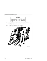
Страница 47: ...ing the RA7000 Storage Enclosure 2 1 3 Removing the RA7000 from the Pallet Use the following procedure to remove the storage cabinet from the shipping pallet WARNING Serious personnel injury may resul...

Страница 48: ...Pallet 2 Lift the lock lever on each front caster to its up position so that the storage cabinet can be moved WARNING We recommend that three people be assigned to the task of unloading the cabinet fr...

Страница 49: ...g container and all packing materials 2 1 4 Placing the RA7000 Storage Enclosure Use the following procedure to move the storage cabinet to its designated site WARNING To prevent damage to the cabinet...

Страница 50: ...te space is available in front of the enclosure for opening the front door and around the enclosure for adequate airflow See Figure 2 4 for specific space requirements Figure 2 4 Minimum Installation...

Страница 51: ...ides an international de skidding label showing how to de skid the cabinet Under the first layer of shrink wrap is the international unpacking labels showing how to unpack the ESA10000 and further ins...

Страница 52: ...ufficient personnel can result in personnel injury and equipment damage The following procedure along with the international unpacking label and Figure 2 5 will help you to remove the ESA10000 from th...

Страница 53: ...s and metal hardware should be inspected for the following defects Cracks more than 25 percent of the ramp depth either across or lengthwise on the ramp Knots or knotholes going through the thickness...

Страница 54: ...01 Figure 2 6 Shipping Pallet Ramp Installation 4 Extend the ramps to their full length 5 See Figure 2 7 for the location of the shipping bolts Remove the bolts 6 Remove the shipping brackets shown in...

Страница 55: ...ING The levelers must be raised fully for the cabinet to roll easily down the unloading ramps Failure to do so may result in personnel injury as a result of the cabinet tipping off the pallet or ramp...

Страница 56: ...e required to unload the cabinet from the shipping cabinet Failure to use sufficient personnel may result in injury and equipment damage 8 Carefully roll the cabinet off the pallet and down the ramps...

Страница 57: ...nt ESA10000 cabinets A cabinet joiner kit comes secured within the ESA10000 packaging Use the joiner kit to join two ESA10000 cabinets In the joiner kit are instructions to position the cabinets to re...

Страница 58: ...side panel Repeat Steps 1 through 4 for the other side panel 5 Continue the joining process 6 Position the two cabinets you are about to join next to each other allowing ample room to walk around bot...

Страница 59: ...econd cabinet 14 Roll the two cabinets close together aligning the joiner latches to the joiner receivers 15 Insert the large Allen wrench provided into one of the tool receptacle holes on a bottom la...

Страница 60: ...ighten the locknuts on all four leveler feet Figure 2 9 Leveler Foot Adjustment 2 3 Installing Additional Components The following sections describe the procedures for installing additional components...

Страница 61: ...abinet with the alignment tabs facing the cabinet side panels and with the three protruding studs through designated holes in the SW600 cabinet front vertical rails The rear of the rail has a U shaped...

Страница 62: ...per left rail 4 6 Upper BA370 lower left rail 26 28 Upper BA370 upper right rail 7 9 Upper BA370 lower right rail 24 26 If using Table 2 1 count the holes from the top of the SW600 cabinet Table 2 2 I...

Страница 63: ...SW600 cabinet and over the obvious holes that correspond to the rear mounting holes of the SW600 cabinet s vertical rails as shown in Figure 2 11 Attach the rear of the mounting rails to the SW600 ca...

Страница 64: ...shown in Figure 2 11 Install two ECB Y cables as shown in Figure 2 12 and tie wrap them to the SW600 cabinet s inner vertical rails These cables will be connected to the ECB during a later step in th...

Страница 65: ...lot and one hole Position the bracket so that the slot is towards the front of the BA370 Install the screw into the screw hole and tighten Install the second screw into the screw slot and tighten Note...

Страница 66: ...ac power to the Power Distribution Unit PDU by moving the breaker switch to 0 Disconnect the power distribution unit from the ac power source 2 When you install an additional BA370 into the cabinet y...

Страница 67: ...70 into place by attaching a 5 16 nut over the middle stud on the front of each mounting rail In the rear of the cabinet use a 10 32 screw through the screw holes of the mounting rails and brackets Re...

Страница 68: ...Expansion Enclosure s NOTE One DS BNK37 1E cable kit is required for each expansion unit 2 4 1 Cabling Sequence When adding an expansion BA370 unit the following sequence is suggested 1 Connect all si...

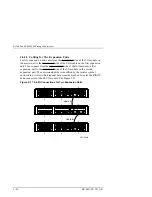
Страница 69: ...ws There is not enough contact pressure to hold the cables in place between enclosures Slide the cable clip along the cable and press it into the hole of the I O module bracket 2 4 2 1 Cabling for One...

Страница 70: ...Then connect from the unterminated side of that I O module on first expansion unit to the terminated side of the I O module on the second expansion unit The unterminated side is identified by the res...

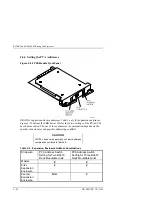
Страница 71: ...E FAULT LED POWER STATUS LED BLOWER FAULT LED S Connect the EMU Communications cable from one EMU communications port See Figure 2 18 of the master RA7000 to the communications port of the first expan...

Страница 72: ...us address switch The use of these addresses in combination depends on the number of enclosures and possible addressing conflicts CAUTION DIGITAL does not support any enclosure address combination not...

Страница 73: ...es CXO5889A ID0 ID6 ID7 ID1 ID2 ID3 Device Address 3 11 15 Device Address 2 10 14 Device Address 1 9 13 Typical Backplane Connection Device Address 0 8 12 Device Address 7 PVA Address 0 2 3 Device Add...

Страница 74: ...aster cabinet to an expansion cabinet route the lower BA370 s SCSI bus cables from I O module number 1 s left port to the expansion cabinet s I O module number 1 s left port Notice for expansion that...

Страница 75: ...Chapter 2 Unpacking and Installation EK SMCPP UG A01 2 31 Figure 2 22 SCSI Bus Cabling for the ESA10000 CXO5931A 6 4 2 5 3 1 6 4 2 5 3 1 6 4 2 1 Expansion cabinet Master cabinet 5 3...

Страница 76: ...right order 4 Repeat this process for the 4GB Disk SBBs 5 Repeat this process for the 2GB Disk SBBs Before beginning the Disk SBB installation process group the Disk SBBs according to capacity If ther...

Страница 77: ...nless the SBB has a device address switch 6 For the addressing of SBB disk drives on the SCSI bus device addresses for each SBB in each extender cabinet are determined by the PVA address The main cabi...

Страница 78: ...he SBB power supply into the guide slots and push in until the power supply is fully seated and the mounting tabs are engaged into the shelf 2 Connect the power cord to the SBB power supply 3 Turn on...

Страница 79: ...r controller failure Use the following procedure to install a new AC power controller Refer to Figure 2 23 1 Press 0 on the AC input power controller ON OFF switch 2 Insert the AC input power controll...

Страница 80: ...binet Refer to Figure 2 24 Figure 2 24 Installing the External Cache Batteries CXO5827A ECB The following procedure details external cache battery installation 1 Insert the external cache battery into...

Страница 81: ..._EMU command to establish the following Enclosure backplane temperature sensor set points on all enclosures SENSOR_1 or SENSOR_1_SETPOINT DEFAULT SENSOR_2 or SENSOR_2_SETPOINT DEFAULT EMU module inter...

Страница 82: ...or reports an over temperature condition You enter the desired temperature in degrees Celsius C within the range of 0 C 32 F through 49 C 120 F See Table 3 3 for the relationship between C and F Fahre...

Страница 83: ...EMU 3 1 3 Setting the Blower Speed Control The UltraSCSI enclosure blowers normally operate at low speed and provide sufficient air flow to cool the enclosure components and ensure proper operation Yo...

Страница 84: ...or 2 a blower is removed NOTE Removing a blower significantly changes the air flow pattern within the enclosure This can cause an over temperature condition in a very short time Therefore this condit...

Страница 85: ...existing fault clears and re occurs When you press and hold the switch for at least 5 seconds you clear all the fault codes NOTE The Alarm Control switch does not affect either the error condition or...

Страница 86: ......

Страница 87: ...list of FRUs 4 1 Storage Subsystem Error Reporting There are multiple light emitting diodes LEDs that display error conditions The two most easily observed are the subsystem front panel Figure 4 1 You...

Страница 88: ...ubsystem Status LEDs RA7000 Shown NOTE The ESA10000 cabinet has Subsystem LEDs mounted in the cabinet door and in a small panel above each BA370 Rack Mountable Enclosure The cabinet door LEDs permit t...

Страница 89: ...nded Corrective Actions Check the EMU control panel LEDs to determine which component has failed 2 Check the host to determine and replace the failed component The subsystem does not have power applie...

Страница 90: ...r the audible alarm sounds the user should check the EMU status LEDs to determine the problem CAUTION Should the audible alarm sound but the status LEDs not indicate an error condition it possible tha...

Страница 91: ...System Fault the temperature status overtemperature error conditions enclosure fault and the status of the individual blowers and banks of blowers When the enclosure is functioning properly only the P...

Страница 92: ...mplete first corrective action If it does not correct the problem complete the second Determine and correct the cause of this condition as quickly as possible to prevent the over condition from causin...

Страница 93: ...ve Action Complete first corrective action If it does not correct the problem complete the second Replace the missing blower Remove and install blowers correctly within 8 minutes Replace defective blo...

Страница 94: ...y press the Alarm Control switch the EMU initiates the following actions 1 Displays the first reported hexadecimal fault code on the blower LEDs three times in succession The LEDs display the first re...

Страница 95: ...ective action If it does not correct the problem complete the second Load microcode image to EMU from maintenance terminal Replace EMU Error Code 03 Either a PVA SCSI ID switch setting is invalid 4 5...

Страница 96: ...defective cable Replace EMU Error Code 05 Master EMU cannot communicate with controller Corrective Action Complete first corrective action If it does not correct the problem complete the second Repla...

Страница 97: ...Enclosure 2 Second Expansion Enclosure 3 Replace each PVA in sequence until the fault condition clears Error Code 09 EMU installed in PVS slot Corrective Action Install EMU in left slot Error Code 0A...

Страница 98: ...d Correction Action Replace EMU Controlled Power Shut Down Display Error Code 0F Fewer than four operational power supplies Comment The EMU initiates a controlled power shut down when this condition o...

Страница 99: ...the controlled power shut down state Enables the Alarm Control switch power on function During a controlled power shut down the Alarm Control switch functions as an enclosure power switch When a cont...

Страница 100: ...ster EMU is not communicating with the controller or the controller does not support a controlled power shut down the master EMU commands all enclosures to perform an immediate power shut down 1 The E...

Страница 101: ...e EMU changes its status to indicate that the dc power switch was pressed 2 The master EMU notes the change in status NOTE When the master EMU is not communicating with the controller or the controlle...

Страница 102: ...the controller The amber port LEDs are OFF when the bus is functioning properly A port LED that is ON or FLASHING indicates that a device on the bus is not functioning properly 4 5 Storage Device Faul...

Страница 103: ...ition When the green Device Activity LED is OFF and the amber Device Fault LED is OFF the device is inactive and the SBB is operating normally no fault condition Fault Status When the green Device Act...

Страница 104: ...s The power supply SBB status is All the power supply SBBs on the associated power bus A or B are functioning properly At least one power supply SBB on the associated power bus has malfunctioned This...

Страница 105: ...ts single ended UltraSCSI buses Therefore you can only use single ended I O modules Installing any other module type creates an error condition that the EMU reports to the controller 4 7 2 No I O Modu...

Страница 106: ...d external TERMPOWER LEDs are ON during normal operation Whenever there a TERMPOWER over current condition the associated LED is OFF When there is an internal TERMPOWER over current condition you must...

Страница 107: ...routine ESD protection procedures when handling controller modules and cache modules and when working around the cabinet and shelf that houses the modules Follow these guidelines to further minimize E...

Страница 108: ...t Down the System Unmount from the host system any units that are accessed through the RAID Array that is about to be repaired Follow the proper procedures to shutdown the host system 5 3 Controller M...

Страница 109: ...5 6 1 2 3 4 5 6 Controller module A Controller module B Cache module A Cache module B 4 With a small blade screwdriver loosen the captive screws on the trilink connector and remove the trilink from t...

Страница 110: ...ll the lever on each side of the module to release it from the card cage 7 Slide the module out of the shelf noting which rails the module was seated in and place on an approved ESD work surface or ma...

Страница 111: ...proved ESD work surface or mat WARNING Do not allow the write back cache to contact any conductive surface or injury and or equipment damage may result Use the following procedure to install the write...

Страница 112: ...the SCSI bus speed and the device transfer rate Figure 5 4 SBB Identification Label DS RZ1DB VW 9 1GB 20 F20 N CH ID N W The components of the device identification label are defined as follows 1 The...

Страница 113: ...age SBB You must repeat the complete procedure for each SBB you are replacing 5 5 2 Before You Replace a Storage SBB Whenever you replace a storage SBB you must consider the following factors Installi...

Страница 114: ...nsole enable the Auto Spare CLI switch NOTE If the Auto Spare CLI switch is not enabled prior to replacing the SBB the new SBB will not load the proper data CAUTION Always use two hands when removing...

Страница 115: ...bsystem with a blower removed significantly changes the air flow pattern and reduces the air flow through the shelf and is associated devices To prevent an over temperature condition never remove a bl...

Страница 116: ...ower mounting tab not shown Upper mounting tab Perform the following procedure to install a blower see Figure 5 3 1 Orient the replacement blower so the connector and guide pin align with the blower o...

Страница 117: ...nt of the power supply SBB 2 Press the two mounting tabs together to release the SBB from the shelf 3 Use both hands and pull the power supply SBB out of the shelf Figure 5 7 Power Supply SBB Replacem...

Страница 118: ...o OFF 2 Disconnect the ac input power cord 3 Loosen the two retaining screws 4 Pull the power controller from the subsystem Figure 5 8 Power Entry Controller Replacement Perform the following procedur...

Страница 119: ...unit 2 Pull the EMU straight out to disconnect it from the backplane and clear of the subsystem Figure 5 9 EMU Module Replacement Perform the following procedure to install an EMU see Figure 5 6 1 Ins...

Страница 120: ...m the unit 2 Pull the PVA straight out to disconnect it from the backplane and clear of the subsystem Figure 5 10 PVA Module Replacement Perform the following procedure to install an PVA see Figure 5...

Страница 121: ...ller 78 32832 07 2 Environmental Monitor Unit EMU DS BA35X EB 3 AC Power Entry Controller DS BA35X HE 4 Power Supply SBB DS BA35X HH 5 External Cache Backup ECB Single Double DS HS35X BC DS HS35X BB 6...

Страница 122: ...RA7000 and ESA10000 Storage Subsystems 5 16 EK SMCPP UG A01 Figure 5 11 Storage Cabinet Field Replaceable Parts RA7000 Shown Item number 11 the PDU is not shown...

Страница 123: ...arity easy to understand Organization logical sequence of information Layout easy to follow subject matter Indexing easy to locate desired information Errors Noted include page paragraph table or figu...

Страница 124: ......
Отзывы: