24
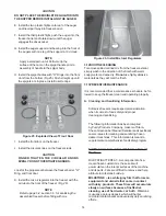
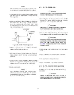
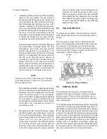
1. Position the E.P.R. valve, with heatsink, so hopper
evaporator outlet line and the line leading to the low
side of the system correspond with the proper valve
ports (Figure 41).
2. Braze the lines to the E.P.R. valve using the
appropriate brazing material.
3. Remove the heatsink from the E.P.R. valve.
4. Replace any foam insulation to the surrounding lines.
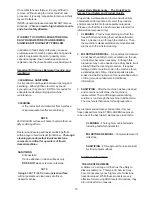
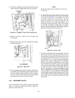
5. Replace the filter drier using the appropriate brazing
material (Figure 42).
Figure 41. E.P.R. Valve and Lines
6. Once the E.P.R. valve and filter drier are installed, the
refrigeration system must be leaked checked, purged
and evacuated to 500 microns of mercury or less at
either barrel outlet access fitting preceding the suction
line solenoid valves.
Figure 42. Filter Drier
4.13
CAPILLARY TUBES
Capillary tube replacement may be necessary if the
correct hopper cooling cannot be obtained. A plugged or
restricted capillary tube or drier will result in a warm
capillary tube at the end going to the hopper when the
freezer is running. Also, the pressure reading at the
E.P.R. valve will equal suction pressure at the
compressor if the tube is totally blocked.
4.14
CAPILLARY TUBE REMOVAL
WARNING
DISCONNECT FREEZER FROM ELECTRICAL
SUPPLY SOURCE BEFORE SERVICING.
1. Remove the Phillips head screws from the left side
and front panels and pull the panels down and out.
2. Recover the refrigerant charge, then leave a port
open to prevent pressure buildup when applying heat.
WARNING
BOTH SUCTION SIDE SOLENOIDS MUST BE
ACTIVATED FOR PROPER PURGING OF
SYSTEM. USE POWER CORD PART NO.
430119
OR EQUIVALENT FOR DIRECT
CONNECTION.
3. Unsweat capillary tube drier assembly at the drier
inlet and at the hopper inlets.
NOTE
Before unsweating capillary tubes at the hopper
inlets, it will be necessary to remove the foam
insulation from the capillary at that connection.
4. Remove the capillary tube drier assembly.
4.15 CAPILLARY TUBE INSTALLATION
1. Position the capillary tube drier assembly so the drier
inlet tube is in position to be brazed. Braze using the
appropriate material.
Содержание E131G
Страница 1: ...Model E131G F131G SERVICE MANUAL Manual No 513537 3 Mar 2004...
Страница 2: ......
Страница 14: ...6...
Страница 38: ...30 Figure 51 Power Board...
Страница 39: ...31 Figure 52 Program Module...
Страница 54: ...46...
Страница 66: ...58...
Страница 68: ...60...
Страница 69: ...61 666786...
Страница 70: ...62...
Страница 71: ...63...
Страница 72: ...64...
Страница 73: ...65...
Страница 74: ...66...
Страница 75: ...67...
Страница 76: ...68...
Страница 77: ...69...
Страница 78: ...70...
Страница 80: ......

